Mattress

a mattress and mattress technology, applied in the field of mattresses, can solve the problems of reducing reducing the comfort of sleeping, and limiting the adverse effect of sleeping comfort, so as to improve the durability of the mattress, the effect of effective dispersion of body pressure and reducing the risk of bedores

Inactive Publication Date: 2013-10-10
SUMITOMO RIKO CO LTD +1
View PDF2 Cites 10 Cited by
  • Summary
  • Abstract
  • Description
  • Claims
  • Application Information

AI Technical Summary

Benefits of technology

[0011]The present invention has been developed in view of the background described above, and it is an object of the present invention to provide a mattress with a novel structure whereby the usability of the mattress is improved, while the prevention of bedsores is effectively achieved by means of dispersed body pressure.

Problems solved by technology

When a user, who has a difficulty in turning over in bed, continues to use a conventional mattress for a long period of time, reaction forces against the body pressure (due to the body weight) are exerted continuously on the user's body part, thus posing a risk of developing bedsores caused by interrupted blood circulation and the like.
However, the mattress described in Japanese Patent No. 2615206 is provided with a support member that connects cells with each other in order to keep each cell in a given direction, and deformation of the cells was too restricted to an approximately vertical direction to provide enough dispersion of the body pressure.
In other words, the structure of the mattress described in Japanese Patent No. 2615206 had a risk of developing bedsores by concentrated body pressure around the contact portion between the outer periphery of the cells and the human body, for example, due to the surface configuration of the mattress capable of following the body contour having a curvy and smooth shape only in a series of steps.
In addition, deformation and displacement of the mattress surface in the planar direction is restricted by the mutual positioning of the cells by the support member in the planar direction of the mattress, which generates frictions between the user and the mattress surface when the user moves his body in the planar direction of the mattress, thus posing a risk of developing bedsores.

Method used


Image

  • Mattress
  • Mattress
  • Mattress

Examples


Embodiment Construction

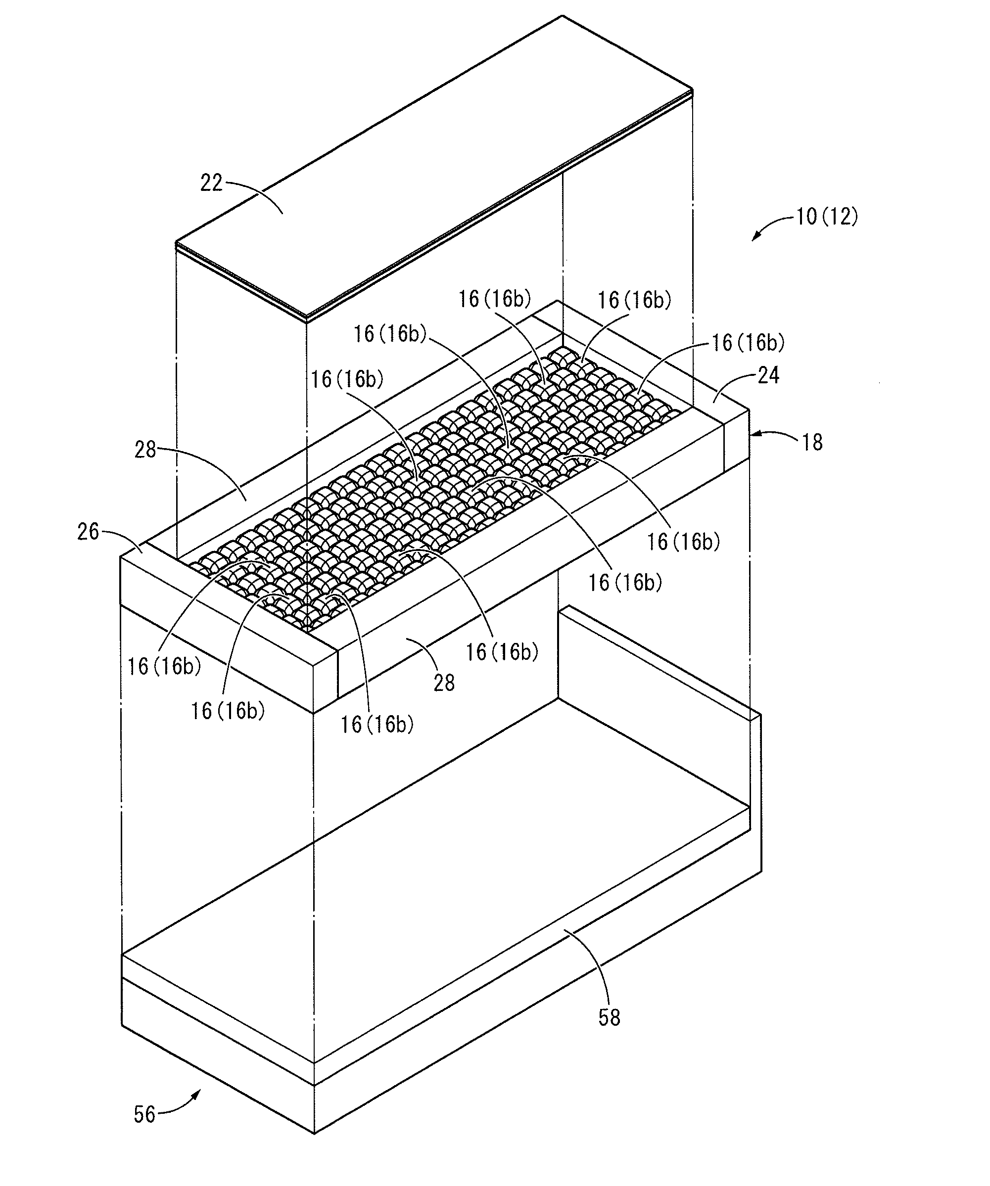
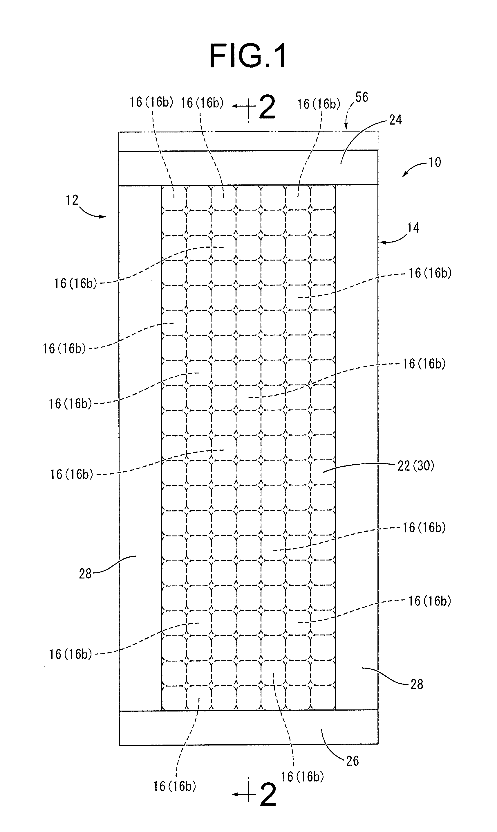
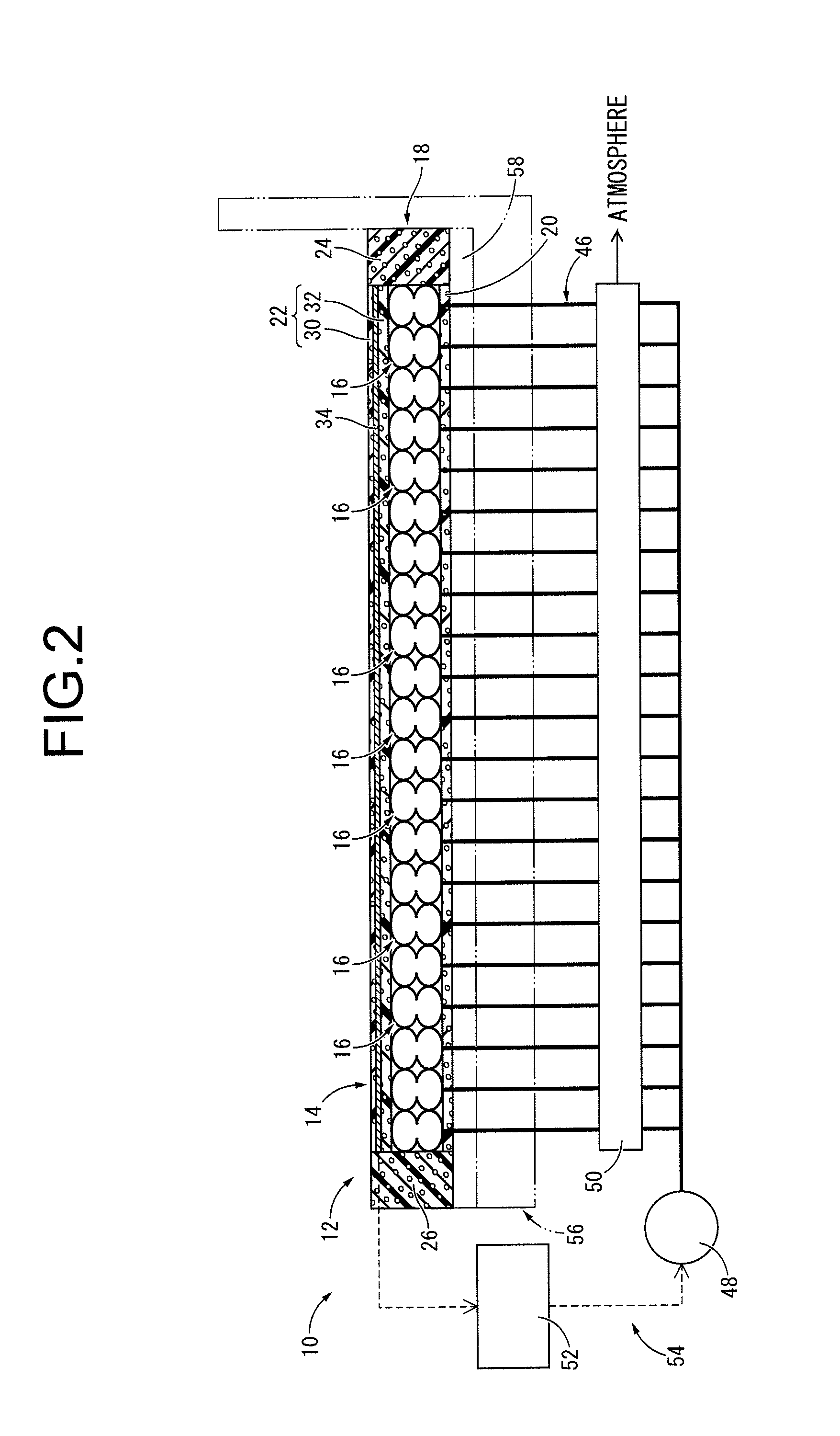
[0041]FIGS. 1 and 2 show a mattress 10 as one of the embodiments of the present invention. The mattress 10 comprises a mattress main body 12, which in turn comprises a box-like housing 14 and a plurality of cells 16 contained in the housing 14. In the following descriptions, the word “up and down direction” generally means an up and down direction in FIG. 2, which is a vertical direction therein.

[0042]More specifically, the housing 14 is formed entirely with an elastic cushion material, and a bottom mat 20 is embedded as a substrate in the lower opening of a framework 18, while a top mat 22 as a cushion layer is embedded in the upper opening of the framework 18.

[0043]The framework 18 is an elastic member formed entirely with porous urethane foam and structured with a head side block 24 and a foot side block 26 arranged parallel to each other that are connected by a pair of side blocks 28 and 28 in a shape of a rectangular framework viewed in the up and down direction. The material m...


PUM


Abstract

The objective of the present invention is to provide a mattress including a plurality of cells provided on a body pressure working surface of a substrate that supports a human body, and a pressure control means that changes a setting of a height of each cell by adjusting a pressure in a fluid chamber formed within the cell. An elastic cushion layer is provided on a body pressure working surface of the cells, and a constricted portion is formed in a middle in the height of the each cell so that the body pressure working surface of the cell is allowed to tilt following deformation of the cushion layer as a result of the cells' precession-deformation at the constricted portion.

Description

INCORPORATED BY REFERENCE[0001]The disclosure of Japanese Patent Application No. 2011-165305 filed on Jul. 28, 2011 including the specification, drawings and abstract is incorporated herein by reference in its entirety. This is a Continuation of International Application No. PCT / JP2012 / 004816 filed on Jul. 27, 2012.BACKGROUND OF THE INVENTION[0002]1. Field of the Invention[0003]The present invention relates to a mattress used for a nursing care bed and the like.[0004]2. Description of the Related Art[0005]Conventionally, in a part of a bed for supporting the human body, a mattress with a cushion function has been used to improve the comfort of sleeping by elastically supporting the human body. This type of mattress is made of elastic materials such as urethane foam, for example.[0006]When a user, who has a difficulty in turning over in bed, continues to use a conventional mattress for a long period of time, reaction forces against the body pressure (due to the body weight) are exert...

Claims


Application Information

Patent Timeline
Patent Type & Authority Applications(United States)
IPC IPC(8): A47C27/08
CPCA47C27/083A61G2203/44A61G7/05769
Inventor MISAKI, AKITSUGUTAKASUGI, SHIN-ICHIROFUKAGAWA, SHUJIWADA, MIKAHARADA, KIYOEMIYAZAKI, KEIKOTACHIBANA, YUKIKOIWAMOTO, YUKIHIDE
Owner SUMITOMO RIKO CO LTD
Why Eureka
Try Eureka