
Device for vacuum packaging, particularly of food products

Active Publication Date: 2013-10-10
DAVINCHY SRL +1
View PDF6 Cites 15 Cited by
  • Summary
  • Abstract
  • Description
  • Claims
  • Application Information

AI Technical Summary

Benefits of technology

The present invention is a device that can quickly and easily vacuum package or seal various technical or food products in trays. It meets several technical requirements, including the ability to achieve vacuum packaging or compensated vacuum without any need for machine stops, as well as optimal heat-sealing of the tray. It is structurally simple and easy to use by even untrained operators, and avoids the need for machine stops and waste of time for cleaning and replacing the die.

Problems solved by technology

Moreover, considerable labor is required.
Operating steps therefore occur which increase the time required to achieve vacuum packaging of the product.
Furthermore, if packaging occurs in a controlled atmosphere, a large proportion of the gas is wasted, since the gas is dispersed not only into the pouch but mostly also inside the vacuum chamber.
However, this solution is complicated, in that it has multiple and distinct stations for performing the individual operations to which the film of plastic material must be subjected in sequence.
Furthermore, hot or cold forming of the plastic film is provided, and so is the filling, by means of a nozzle, with liquid products, flours or finely granulated products, and therefore it is not possible to consider the use of the described solution for solid products having preset volumes, such as sliced ham and salami, meat, cheese in portions, trays containing food and nonfood products.
This solution, too, is not free from drawbacks, since the forming of micro-creases has been observed during the heat-sealing of the film, and this can entail problems in tightness and worsens the aesthetic appearance of the package.
Furthermore, the flow of the gas inside the film is not optimum, reducing the efficiency of the device.
Finally, when the operator pulls the sheet, the sheet can assume an incorrect arrangement.
Another problem is also noted: when vacuum is provided in a bell, and accordingly in the pouch being formed, it is then necessary to compensate the vacuum partially with the gas; however, if the compensation is excessive, the bell opens during heat-sealing.
The quantity, both in absolute terms and in relative terms (%), of gas that remains inside the pouch being formed is therefore extremely variable and difficult to control, and this leads to the provision of a series of pouches or packages which are more or less inflated or deflated depending on the situation.
The problem is then worsened if it is necessary to change package format often.
Another problem is observed in the step of heat-sealing of the film, which is heat-sealed and cut on the transverse side with respect to the direction of advancement of the film: since it is often made of heat-shrinking material, the film can retract, reducing its width, and this might prevent the accommodation of the oncoming tray.
The tray can thus arrive and find a space that is insufficient to accommodate it, and this causes its diversion toward the open side of the pouch, ending on the longitudinal heat-sealing bar, causing machine downtimes and waste of time for cleaning the machine.
Finally, it is noted that the return of the air into the bell or vacuum chamber occurs, due to constructive reasons, usually in a region that is far from the heat-sealing bar or coincides with the vacuum hole by means of the use of a three-way valve, but this does not optimize the conveyance of the flow inside the bell.
The problem that is observed is constituted by the considerable time required to change the die as a function of the shape of the tray to be heat-sealed.
This solution is mechanically very complicated and expensive, and it also has processing downtimes that affect the overall costs of the machine.

Method used


Image

  • Device for vacuum packaging, particularly of food products
  • Device for vacuum packaging, particularly of food products
  • Device for vacuum packaging, particularly of food products

Examples


first embodiment

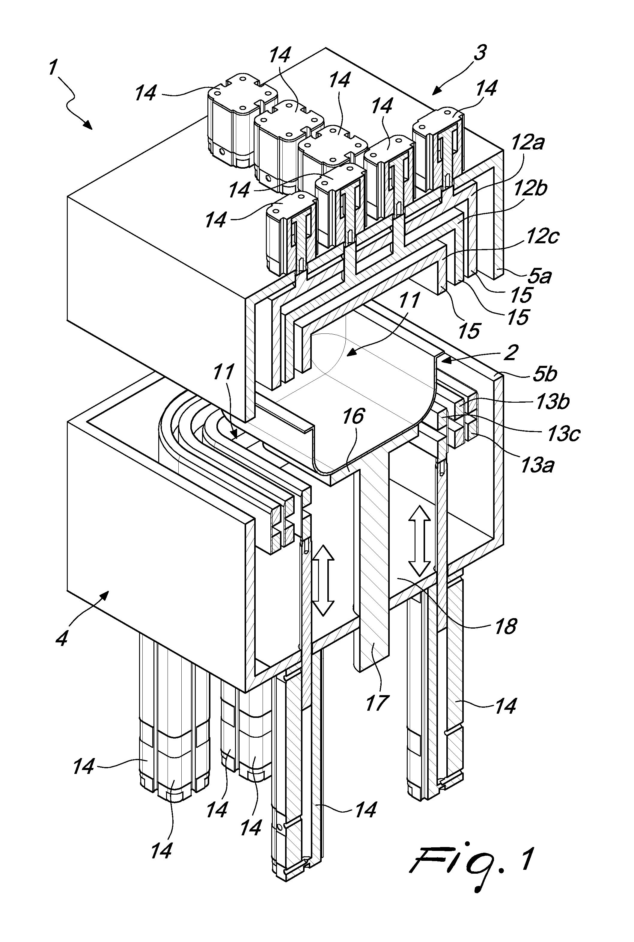
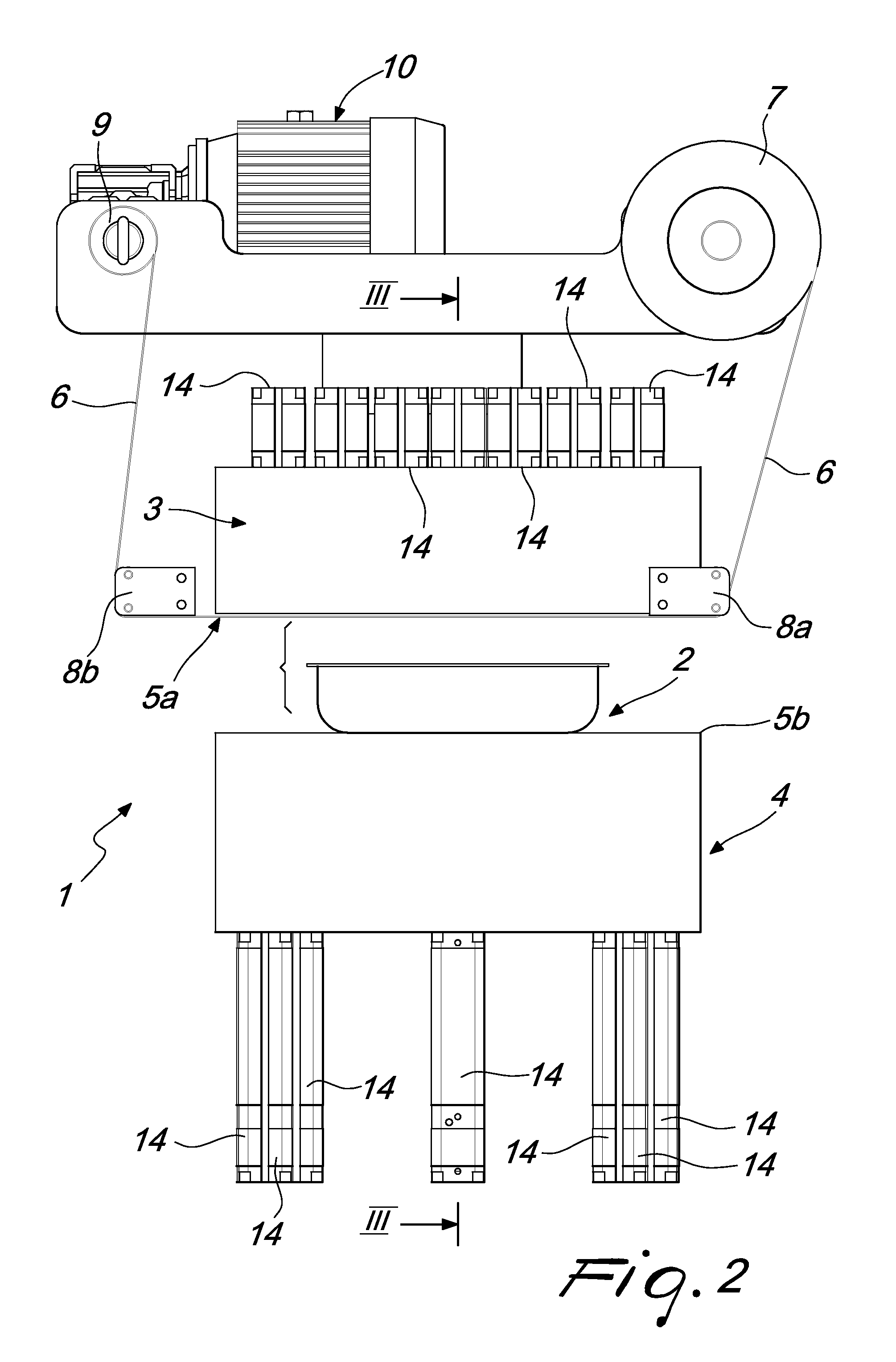
[0081]Therefore, differently from the first embodiment, the heat-sealing and / or cutting and / or die-cutting occurs exclusively by moving the lower chamber toward the upper chamber, without actuating for lowering the individual heat-sealing and / or cutting and / or die-cutting means of the upper chamber.

second embodiment

[0082]Essentially, in this second embodiment there are no presser means at the upper chamber.

[0083]The film used can be both of the single-folded type and of the flat sheet type.

[0084]The materials used, as well as the dimensions that constitute the individual components of the invention, may of course be more pertinent according to specific requirements.

[0085]The various means for performing certain different functions need not certainly coexist only in the illustrated embodiment, but can be present per se in many embodiments, including ones that are not illustrated.

[0086]The characteristics indicated as advantageous, convenient or the like may also be omitted or be replaced with equivalents.


PUM

PropertyMeasurementUnit
Sizeaaaaaaaaaa
Dimensionaaaaaaaaaa
Heightaaaaaaaaaa

Abstract

A packaging device, particularly for packaging trays containing food products or technical materials in a controlled atmosphere and by means of a film of plastic material, comprising an upper chamber and a lower chamber, which can be fastened by mutually superimposing them and are each provided internally with a plurality of heat-sealing and / or cutting and / or die-cutting elements arranged concentrically, the lower chamber being provided centrally with a plurality of supporting elements for a tray.

Description

TECHNICAL FIELD[0001]The present invention relates to a packaging device, particularly for food products or technical materials.BACKGROUND ART[0002]Vacuum machines are currently known which have a bell-shaped chamber and comprise a vacuum pump which is connected to a chamber, also known as vacuum chamber, inside which there is usually a preformed pouch, which is open on three sides and inside which a food product is placed.[0003]In these machines of the known type, the preformed pouch, with the product already inside, is then inserted in the vacuum chamber and then vacuum is produced inside the chamber; a heat seal is then provided at the free side of the preformed pouch.[0004]This known technology entails the need to use preformed pouches which therefore have a size that can be compared to that of the product. Moreover, considerable labor is required.[0005]Operating steps therefore occur which increase the time required to achieve vacuum packaging of the product. Furthermore, if pa...

Claims


Application Information

Patent Timeline
IPC IPC(8): B65B7/28
CPCB65B7/2878B65B31/028B65B51/14B65B57/08B65B59/02B65B7/164B65B2210/02B29L2031/712B29C65/18B29C65/7451B29C65/749B29C66/0014B29C66/112B29C66/131B29C66/53461B29C66/81463B29C66/8167B29C66/83221B29C66/8412B29C66/84121B29C66/849B29C65/7461B29C66/8242B65B59/003B65B31/02
Inventor SCOLARO, MAURO
Owner DAVINCHY SRL
Learn More