Draper header and crop divider knife

a technology of draper headers and divider knives, which is applied in the field of crop divider knives for draper headers, can solve the problems of unharvested, relative weakness, and the loss of bedraggled mass hanging from each end of draper headers, and none of these disclose crop divider knives

Inactive Publication Date: 2013-10-10
DEERE & CO
View PDF13 Cites 21 Cited by
  • Summary
  • Abstract
  • Description
  • Claims
  • Application Information

AI Technical Summary

Problems solved by technology

They are also relatively weak.
This enmeshment poses a problem in the crops are harvested.
As the draper header proceeds further down the field, this bedraggled mass hanging from each end of the draper header will eventually be lost and unharvested.
None of these disclose a crop divider knife driven by a gear box that also drives the horizontal reciprocating knife that extends across the leading edge of the draper header adjacent to the ground.

Method used


Image

  • Draper header and crop divider knife
  • Draper header and crop divider knife
  • Draper header and crop divider knife

Examples


Embodiment Construction

[0022]As the terms are used herein, “forward”, “forwardly”, “in front” or similar terms are made in reference to the direction of travel of the draper header as it travels through the field in a straight line harvesting crop. The terms “backward”, “back”, “behind” or similar terms refer to a direction opposite the direction of travel. The terms “lateral”, “laterally”, “side-to-side” and like terms refer to a direction perpendicular to the direction of travel.

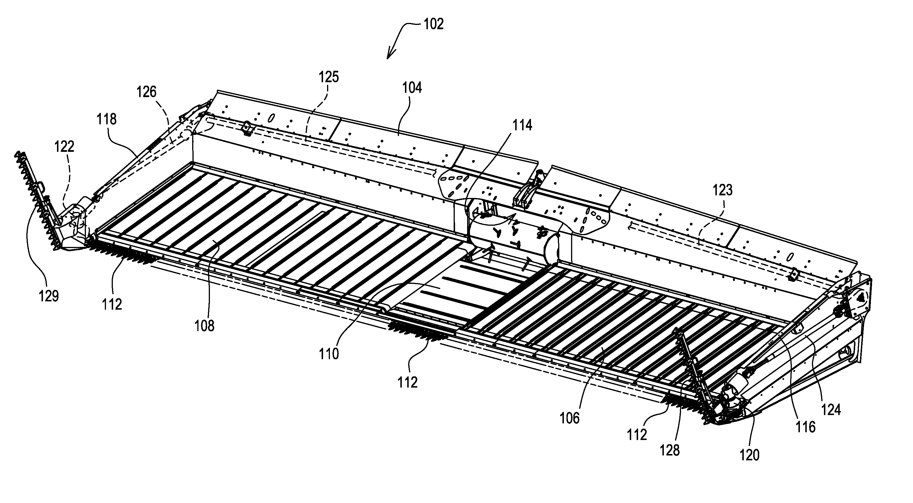
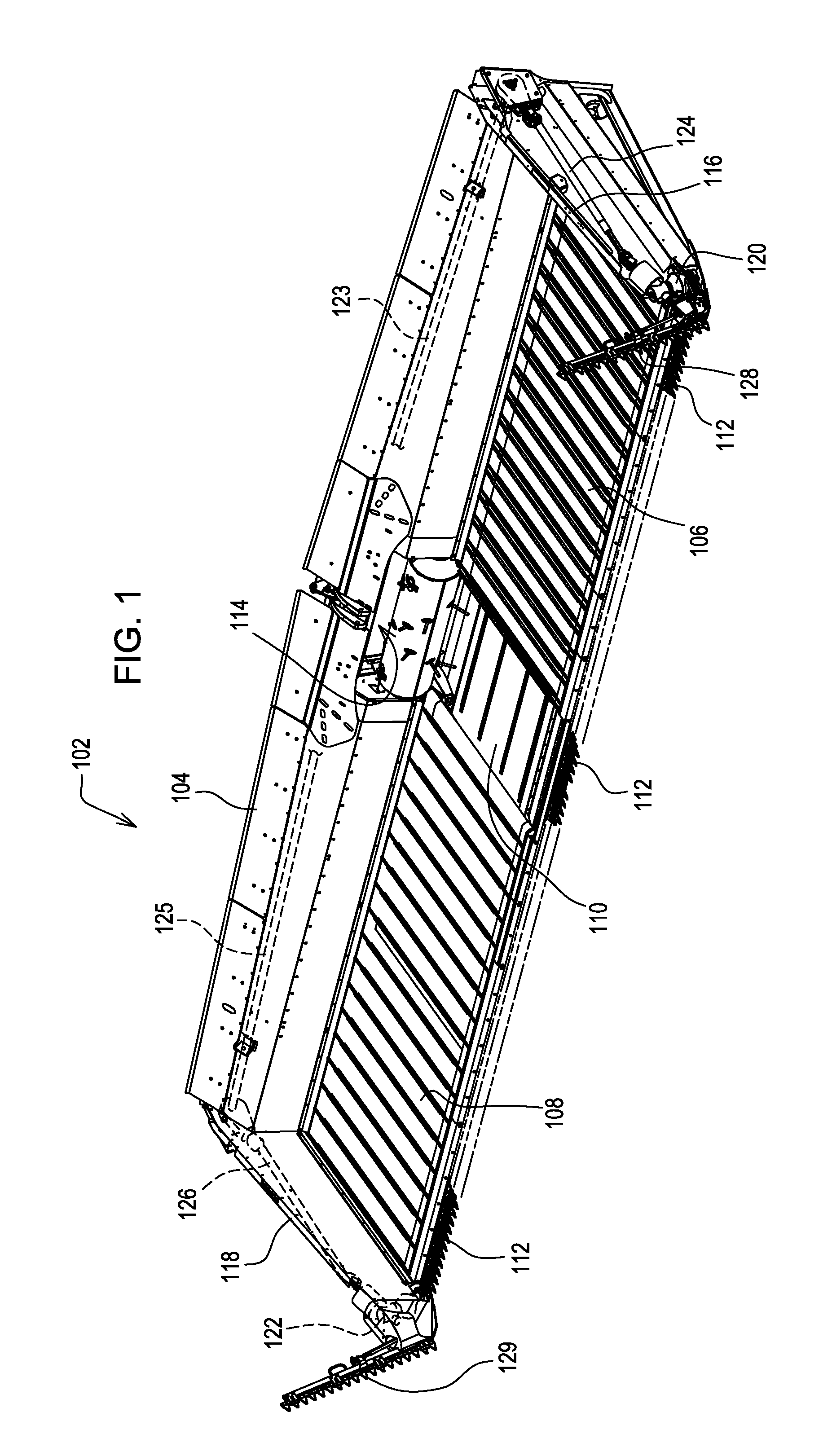
[0023]FIG. 1 shows a draper header 102 for mounting on an agricultural combine (not shown). The draper header 102 has a frame 104 that extends laterally and perpendicular to the direction of travel “V” of the combine through the field. The frame supports left side conveyor 106, right side conveyor 108, and a center conveyor 110.

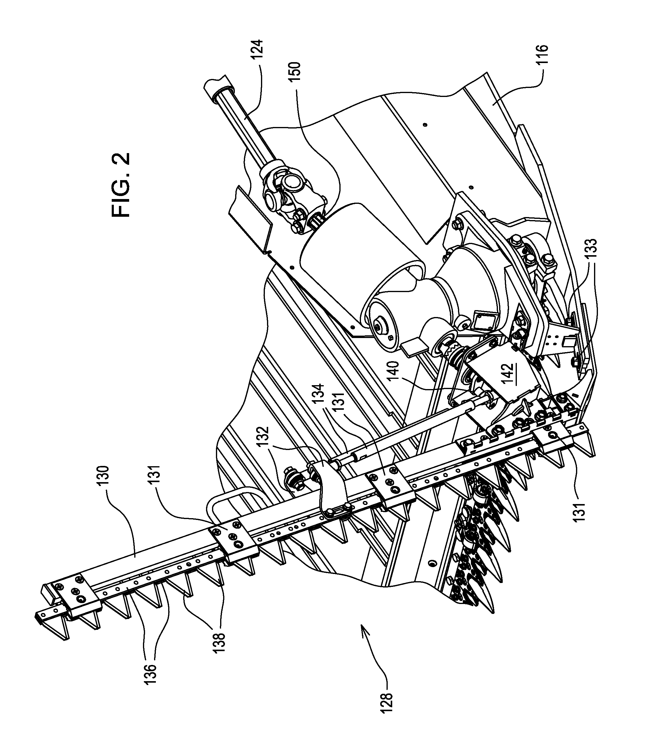
[0024]A reciprocating knife 112 is fixed to a forward edge of the frame (or members that extend forward from the frame) and extends across substantially the entire width of the draper header. The reciproc...


PUM


Abstract

A draper header (102) is provided having the elongate laterally extending frame (104) and two forwardly extending crop dividers (116, 118) at each end. A gear box (120, 122) is mounted on the front of each crop divider (116, 118). The gearbox (120, 122) has two output shafts (148, 152), a first shaft (148) that is coupled to and drives an elongate reciprocating knife (112) extending across the leading edge of the draper header (102) and a second shaft (152) that is coupled to and drives a crop divider knife (128, 129). The crop divider knife (128, 129) includes a quick coupling (144) that engages a quick coupling (154) mounted on the second shaft (152).

Description

FIELD OF THE INVENTION [0001]This invention relates to draper headers for agricultural combines. More particularly, it relates to crop divider knives for draper headers.BACKGROUND OF THE INVENTION[0002]Draper headers are used to cut non-row crops, such as wheat, rapeseed, flax, oats, and soybeans. Draper headers generally have a horizontal and laterally extending frame with a forward edge to which an elongate reciprocating knife is attached. This reciprocating knife includes at least one reciprocating bar to which a plurality of blades are attached that extend across substantially the entire width of the draper header. As these blades are driven in reciprocation, they engage stationary knife guards. The stationary knife guards are fixed to the leading edge of the draper header is well. The reciprocating blades, typically triangular, chop off the stalks of the crop plants very close to the ground. The severed crop plants fall backwards onto a moving conveyor belt which carries them t...

Claims


Application Information

Patent Timeline
Patent Type & Authority Applications(United States)
IPC IPC(8): A01D43/06A01D63/04
CPCA01D34/23
Inventor LOVETT, BENJAMIN M.COON, STEVE A.ANDERSON, SHANE MARTY
Owner DEERE & CO
Why Eureka
Try Eureka