Illumination apparatus, image sensor unit, and paper sheet discriminating apparatus

a technology of image sensor unit and apparatus, applied in the direction of lighting and heating apparatus, instruments, fibre light guides, etc., can solve the problems of illumination apparatus and image sensor unit further enlarged, image sensor unit enlarged accordingly, illumination apparatus and the illumination apparatus enlarged

Inactive Publication Date: 2013-10-10
CANON COMPONENTS INC
View PDF4 Cites 32 Cited by
  • Summary
  • Abstract
  • Description
  • Claims
  • Application Information

AI Technical Summary

Benefits of technology

[0013]An object of the present invention is to provide an illumination apparatus with a reduced protrusion length in a predetermined direction and to provide an image sensor unit, and a paper sheet discriminating apparatus using the illumination apparatus.

Problems solved by technology

When the LED modules with the deviated LED chips are set on both end faces of a light guide, there is a problem that the illumination apparatus is enlarged and that the image sensor unit is enlarged accordingly.
As a result, there is a problem that the illumination apparatus and the image sensor unit are further enlarged.
However, if the LED chips in different shapes are used, the cost is greater than when LED chips in the same shape are used at both ends.

Method used


Image

  • Illumination apparatus, image sensor unit, and paper sheet discriminating apparatus
  • Illumination apparatus, image sensor unit, and paper sheet discriminating apparatus
  • Illumination apparatus, image sensor unit, and paper sheet discriminating apparatus

Examples


first embodiment

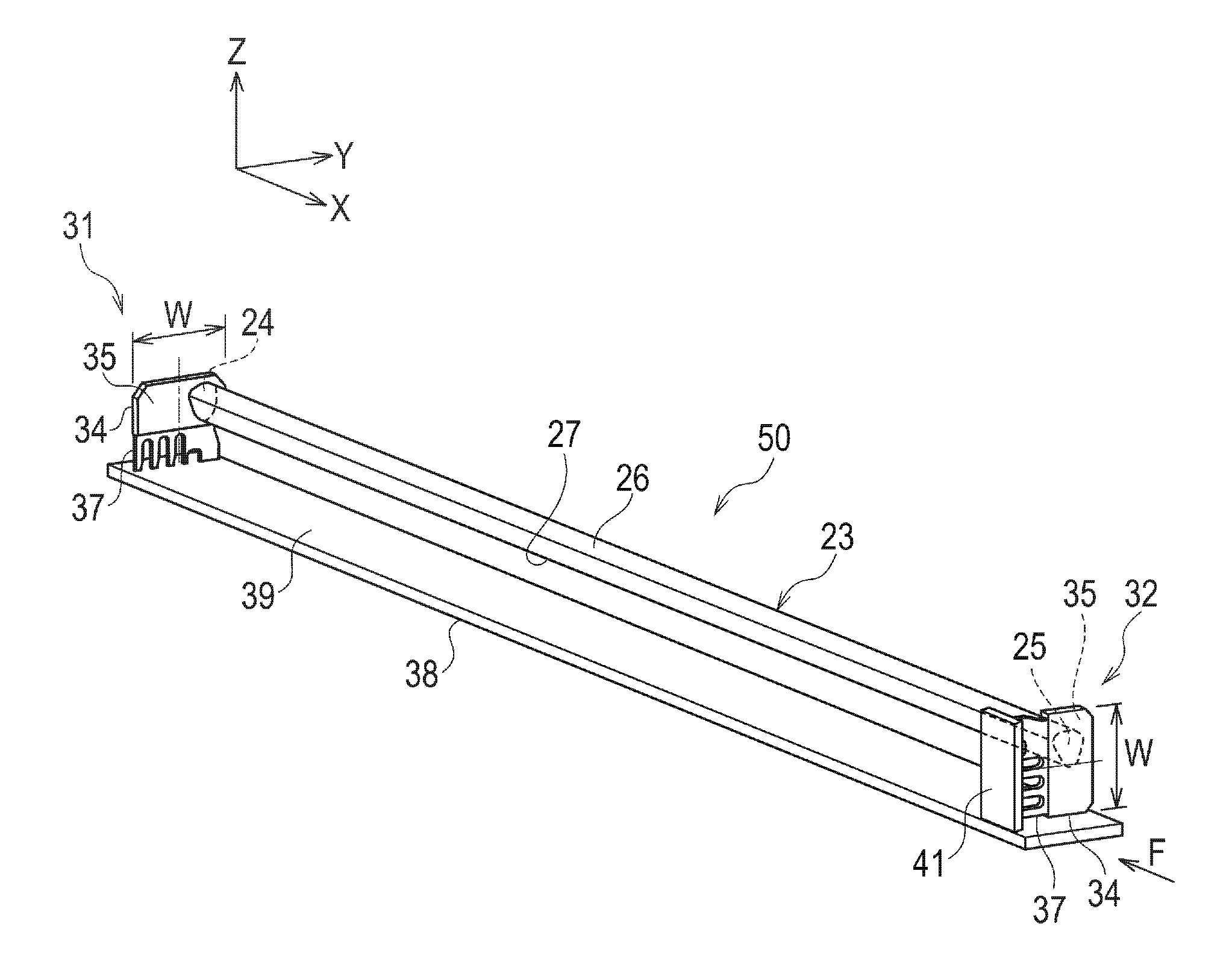
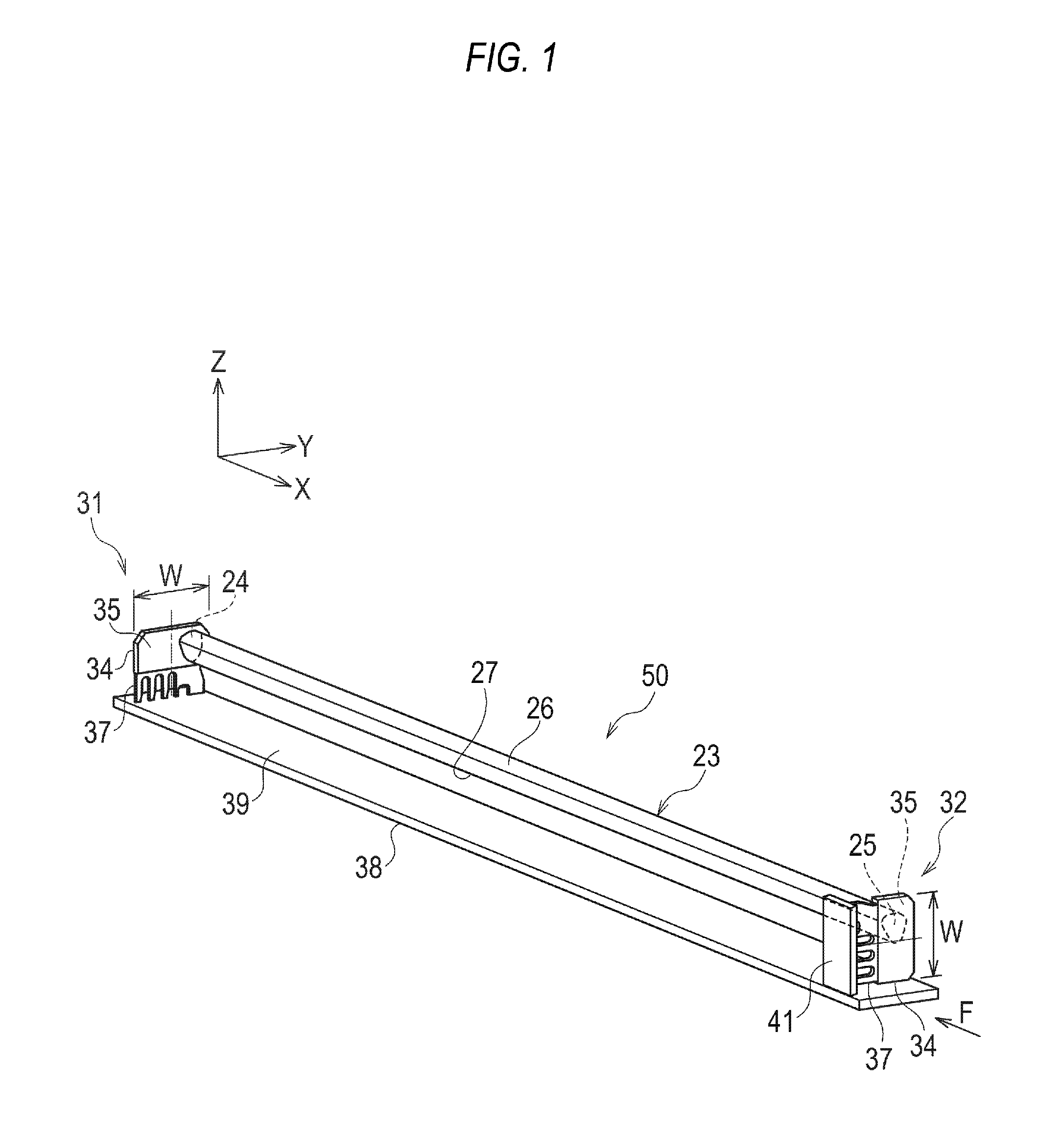
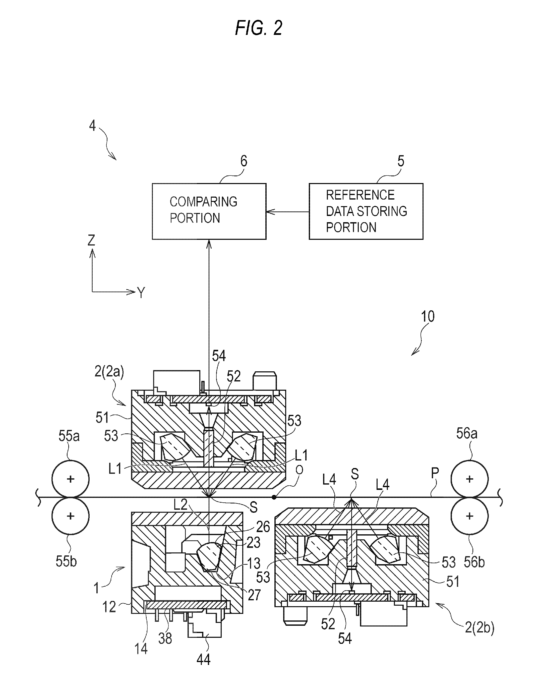
[0048]In the present embodiment, an illumination apparatus, a light source unit to which the illumination apparatus is applied, and a paper sheet discriminating apparatus to which the light source unit is applied will be described. The paper sheet discriminating apparatus 4 authenticates paper sheets such as bills and securities, and the illumination apparatus emits transmitted light to an original P (illuminated body) as a paper sheet.

[0049]FIG. 16 is a perspective view of a paper sheet reading portion 10 including a light source unit 1. FIG. 2 is a sectional view illustrating an example of a configuration of the paper sheet discriminating apparatus 4 including the light source unit 1, and the paper sheet discriminating apparatus 4 includes the paper sheet reading portion 10. At predetermined parts of the paper sheet reading portion 10, conveyor rollers 55a and 55b and conveyor rollers 56a and 56b for conveying, in a pair, an original P held therebetween are arranged spaced apart f...

second embodiment

[0095]In the present embodiment, an image sensor unit including the illumination apparatus 50 according to the first embodiment as well as an image reading apparatus and an image forming apparatus to which the image sensor unit is applied will be described. In the image reading apparatus and the image forming apparatus, the illumination apparatus 50 emits light to the original P as an illuminated body, and the image sensor unit including the illumination apparatus 50 converts reflection light to an electric signal to read an image.

[0096]A multifunction printer (MFP) as an image reading apparatus or an image forming apparatus, to which the image sensor unit according to the present embodiment can be applied, will be described with reference to FIG. 9. FIG. 9 is a perspective view illustrating an appearance of the MFP. As illustrated in FIG. 9, the MFP 60 includes: an image reading portion 62 as image reading means for reading reflection light from the original P as an illuminated bod...


PUM


Abstract

A first light source and a second light source are arranged so that a protrusion direction of a first terminal from a first supporting body and a protrusion direction of a second terminal from a second supporting body are different when viewed in the longitudinal direction of a light guide. The first light source and the second light source are arranged so as to reduce a protrusion direction of the first supporting body and the second supporting body in a predetermined direction from an area where the first light source and the second light source overlap when viewed in the longitudinal direction of the light guide.

Description

CROSS-REFERENCE TO RELATED APPLICATIONS[0001]This application is based upon and claims the benefit of priority of the prior Japanese Patent Application No. 2012-085853, filed on Apr. 4, 2012, and the Japanese Patent Application No. 2013-073139, filed on Mar. 29, 2013, the entire contents of which are incorporated herein by reference.BACKGROUND OF THE INVENTION[0002]1. Field of the Invention[0003]The present invention relates to an illumination apparatus, an image sensor unit, and a paper sheet discriminating apparatus.[0004]2. Description of the Related Art[0005]A light-guide type illumination apparatus is known as an illumination apparatus used in an image sensor unit.[0006]Japanese Laid-open Patent Publication No. 9-214675 discloses a light source unit (illumination apparatus) with LED lamps installed on both end faces of a light guide to obtain more light.[0007]An LED module may be used as a light source of the illumination apparatus, the LED module including LED chips arranged o...

Claims


Application Information

Patent Timeline
Patent Type & Authority Applications(United States)
IPC IPC(8): F21V8/00H01L31/16H04N1/00
CPCG02B6/0001H04N1/00005H01L31/16G07D7/00G02B2006/0098H04N1/00525H04N1/02835H04N2201/02495G02B6/001G07D7/121
Inventor MURAKAMI, HIROYUKINAGATA, KENJIKINOSHITA, JUNYA
Owner CANON COMPONENTS INC
Why Eureka
Try Eureka