Vehicular Lamp

Active Publication Date: 2013-10-10
KOITO MFG CO LTD
View PDF2 Cites 11 Cited by
  • Summary
  • Abstract
  • Description
  • Claims
  • Application Information

AI Technical Summary

Benefits of technology

[0007]The present invention is devised in the light of the above circumstance, and it is an object of the present i

Problems solved by technology

Therefore, the light guide appears dark when pedestrians or the like see the lamp from the di

Method used


Image

  • Vehicular Lamp
  • Vehicular Lamp
  • Vehicular Lamp

Examples


Example

[0018]An embodiment of the present invention will be described in detail below with reference to the accompanying drawings.

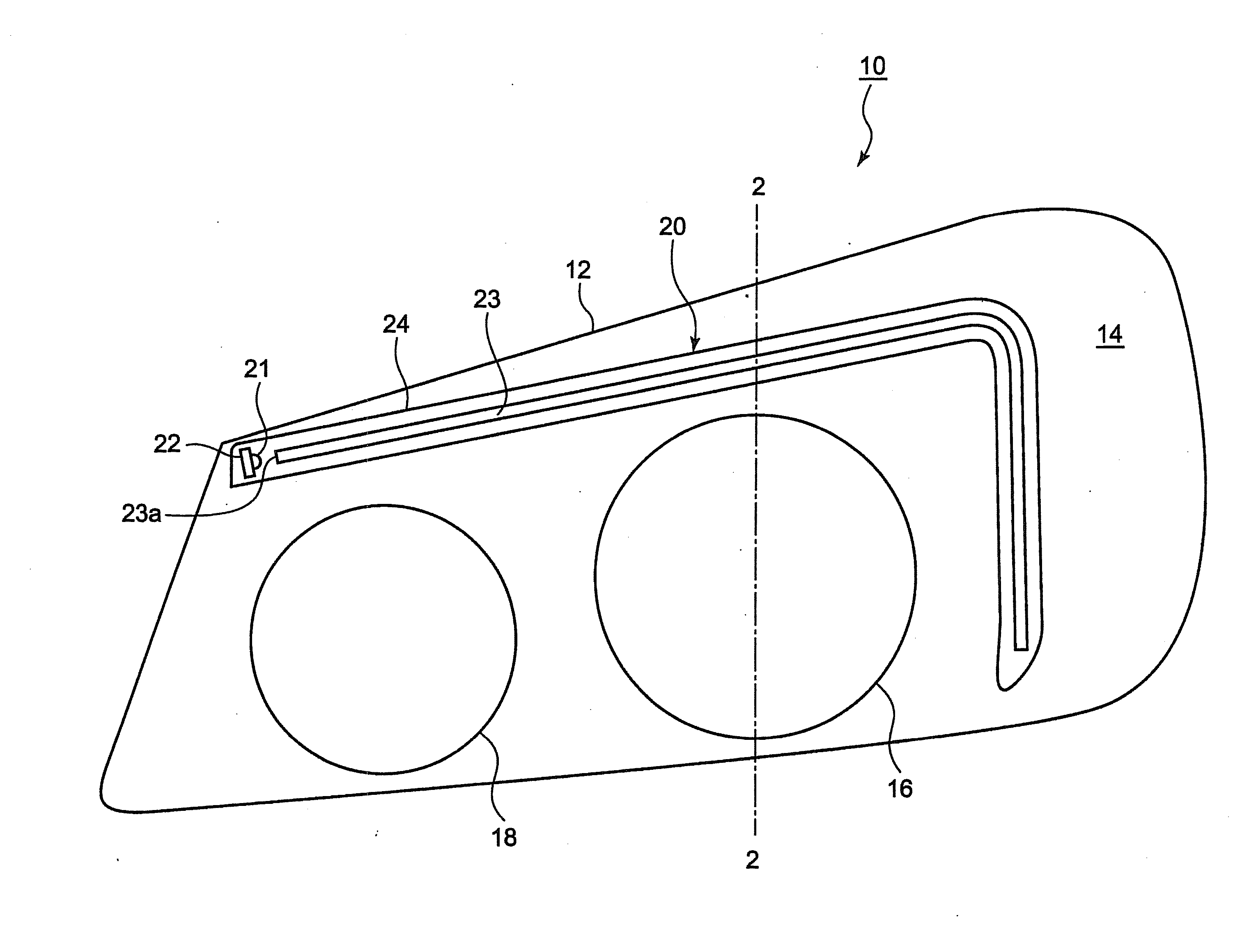
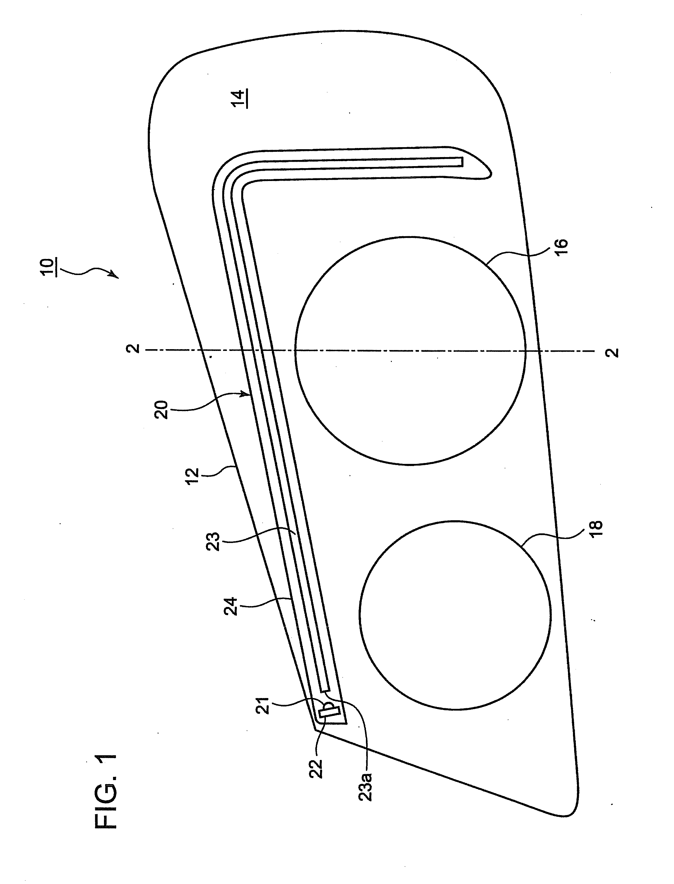
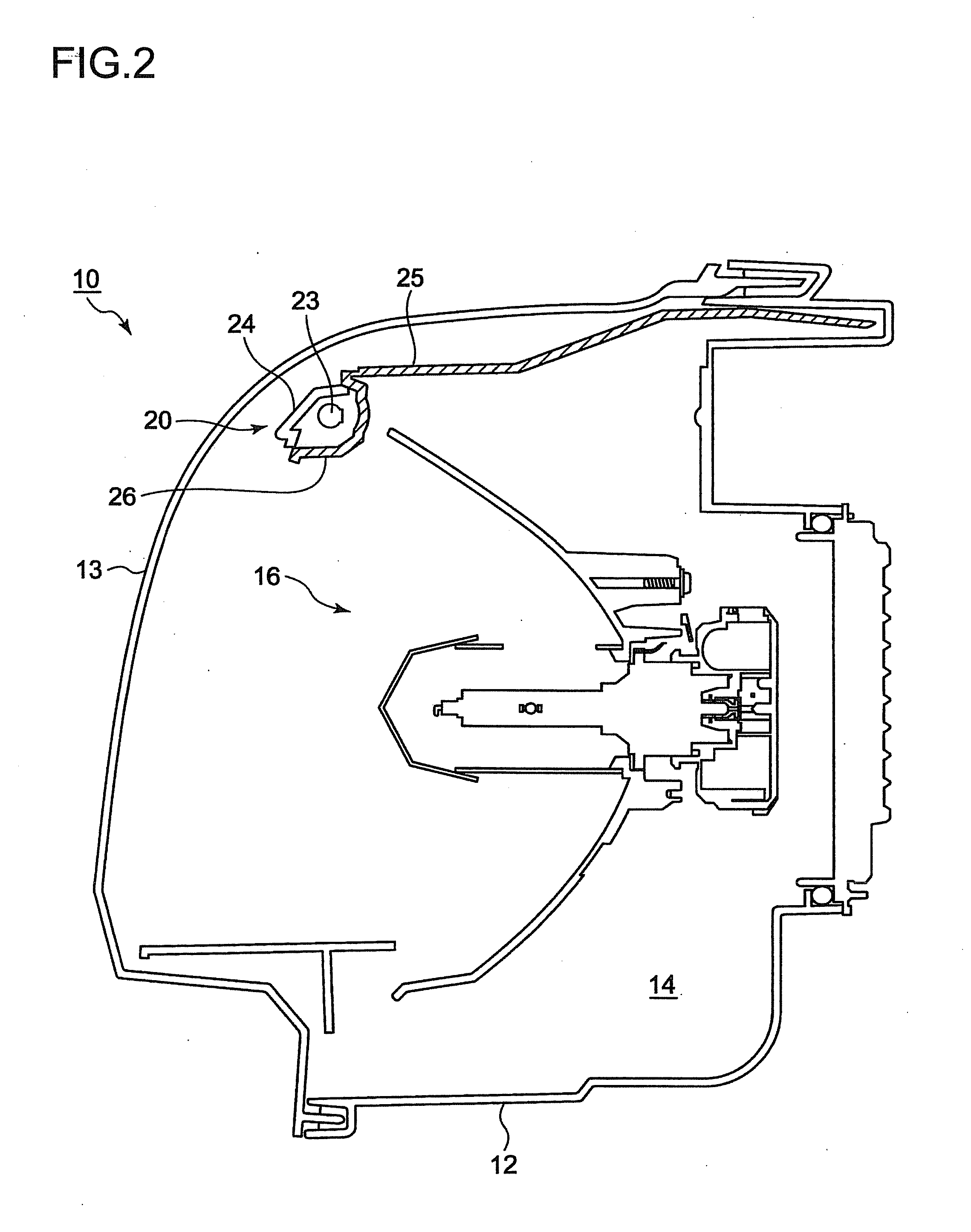
[0019]FIG. 1 illustrates a vehicular headlamp 10 according to the embodiment of the present invention, and FIG. 2 shows in cross section the vehicular headlamp 10 taken along the line 2-2 in FIG. 1.

[0020]As shown in FIG. 1 and FIG. 2, the vehicular lamp 10 is a combination headlamp in which a low-beam lamp 16, a high-beam lamp 18, and a clearance lamp 20 are accommodated inside the lamp chamber 14. The lamp chamber 14 is formed by a lamp body 12 and a transparent cover 13.

[0021]The low-beam lamp 16 and the high-beam lamp 18 are provided side-by-side in a vehicle-width direction within the lamp chamber 14. In FIG. 2, the low-beam lamp 16 is a reflector-type lamp. However, the type of the low-beam lamp 16 is not particularly limited, and it can be, for example, a reflector-type or projector-type vehicular lamp. The reflector-type low-beam lamp is publicly known, a...


PUM


Abstract

A clearance lamp (20) including a light source (21) and a light guide (23) that allows light from the light source (21) to enter from an end face of the light guide (23) and emits the light forward from an emitting surface (23b) while guiding the light in the interior of the light guide (23). The emitting surface (23b) extends along a direction in which the light guide (23) extends. The light guide (23) includes steps (23c) that reflect the light traveling through the light guide toward the emitting surface (23b), and it further includes a light-emitting surface (23d) that is formed at a position different from a position of the light-emitting surface (23b) and emits the light traveling through the light guide to the outside of the light guide.

Description

BACKGROUND OF THE INVENTION[0001]1. Field of the Invention[0002]The present invention relates to a vehicular lamp provided with a light guide and more particularly to a vehicular lamp that includes a clearance lamp having a light guide.[0003]2. Description of the Related Art[0004]In a conventionally known combination headlamp, a low-beam lamp, a high-beam lamp, a clearance lamp, and the like are integrally accommodated inside the lamp chamber.[0005]In this combination headlamp, for example, a projector-type lamp or a reflector-type lamp is used as the low-beam lamp and the high-beam lamp. As the clearance lamp, a reflector-type lamp has been generally employed. In recent years, there has been proposed a clearance lamp that includes a light guide, in which the light guide allows light emitted from the light source such as an LED (Light Emitted Diode) to enter from an end face of the light guide and then emits the light to the outside of the light guide while guiding the light in the ...

Claims


Application Information

Patent Timeline
IPC IPC(8): F21S8/10
CPCF21S48/1241F21S48/115F21S48/215F21S48/24F21S48/2268F21S48/2287F21S48/2237F21S41/24F21S43/14F21S43/237F21S43/245F21S43/247F21S43/40
Inventor SAITO, JUNICHI
Owner KOITO MFG CO LTD
Why Eureka
Try Eureka