
Sensor System of Buried Seismic Array

Active Publication Date: 2013-10-10
NUTEC SCI
View PDF25 Cites 72 Cited by
  • Summary
  • Abstract
  • Description
  • Claims
  • Application Information

AI Technical Summary

Benefits of technology

The present patent describes a surveying method and system that integrates active and passive surveying of a subsurface volume in land-based or marine-based applications. The method involves using seismic sensors to gather data on the subsurface volume and determine its properties. The system detects microseismic events using arrays of sensors placed in boreholes or on the surface. The detected events can be used to adjust the property of the subsurface volume. The technical effects of this patent include improved accuracy in surveying and monitoring of subsurface events, which can aid in energy exploration and production.

Problems solved by technology

Land-based seismic surveys usually do not record extraneous information to assist in the characterization of a shallow earth model.
As expected, drilling an observation well can be costly, and the availability of one or more existing wells for use as observation wells within a suitable distance—usually within 1000 m—may be unlikely in most cases.
Because a microseismic event is detected at the surface, surface noise can be rather large compared to the small event downhole.
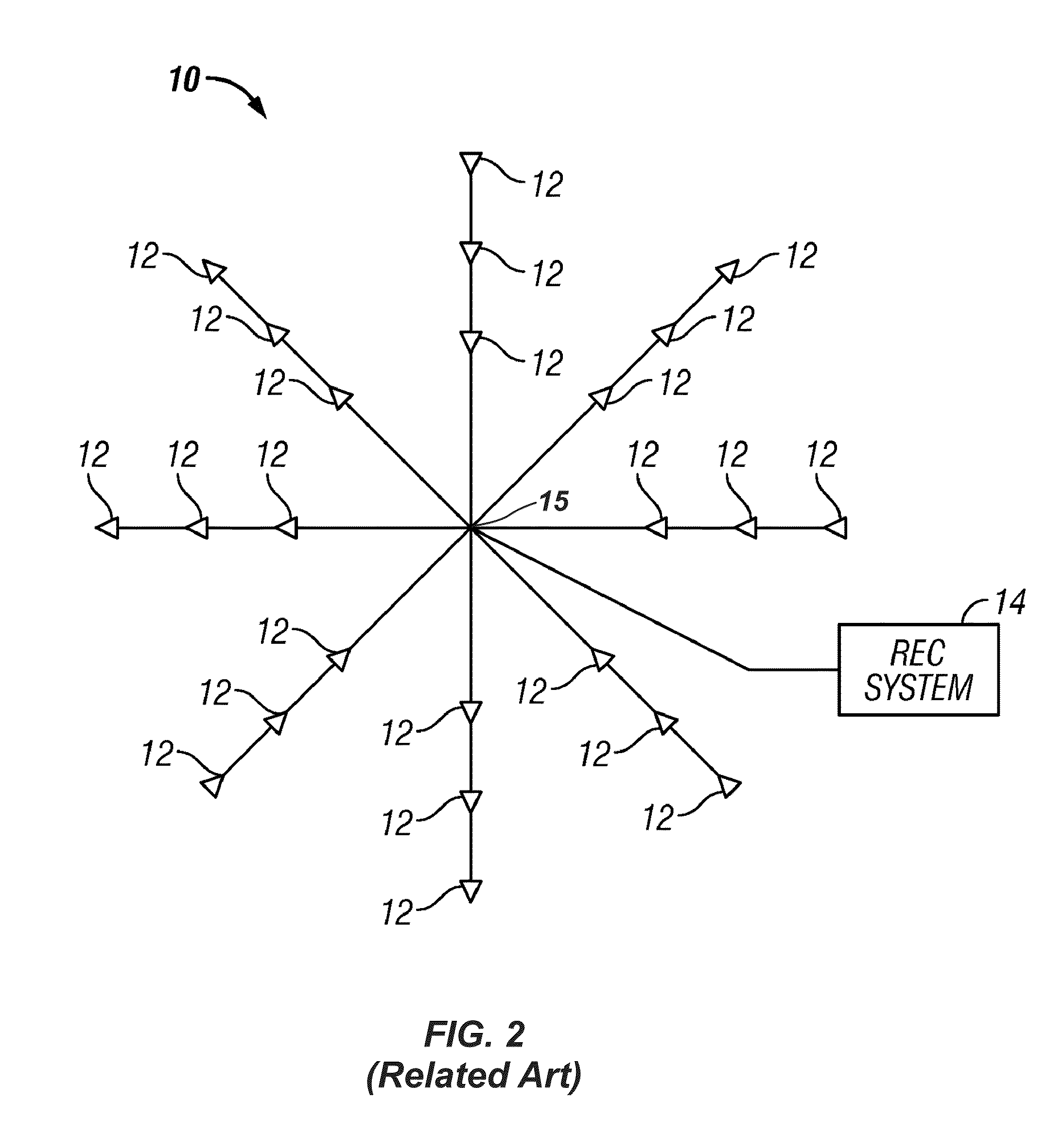
It should be noted that the stacking procedure using beam steering can fail to detect events because the polarity of a microseismic event may not be uniform across the seismic array 10.
Detecting and locating the microseismic event becomes less reliable as noise increases, and differentiating real events (i.e., fractures, earth shifts, etc.) from false positives becomes more difficult.
Although the array 10 of sensors 12 can facilitate imaging the seismic data, the ultimate uncertainty of whether a real microseismic event has been detected makes it difficult to know that what is imaged is an actual event and not just a false positive.
For example, experience shows that production along a lateral section of a well is not uniform.
In fact, any resulting production from a reservoir tends to come from those stages that have been fractured, which may not even include all of the hydraulic fracture stages.
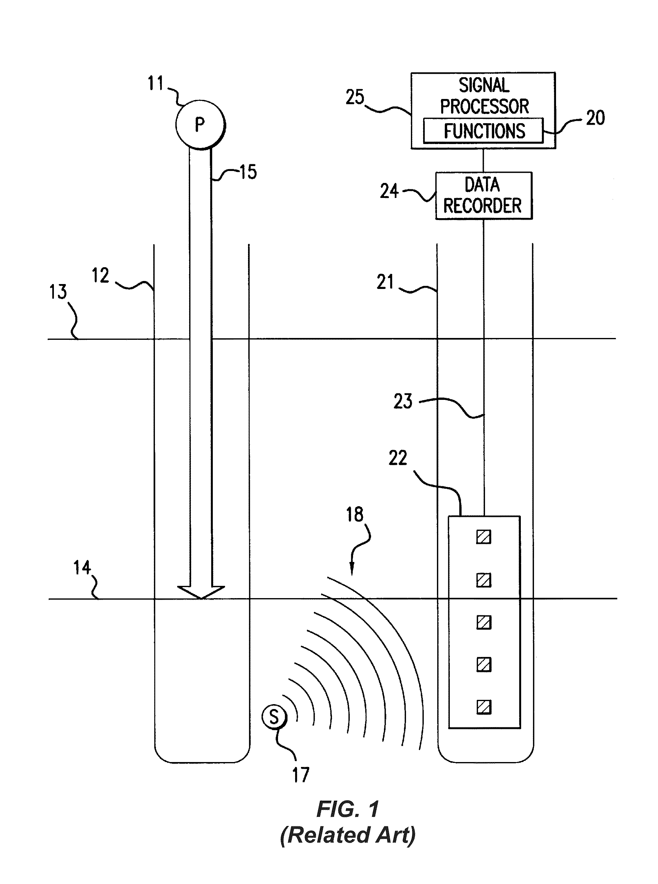
To that end, microseismic monitoring has the ongoing challenge of detecting and recording small signals in a high-noise environment, accurately locating microseismic events, and mapping those events over a wide area.

Method used


Image

  • Sensor System of Buried Seismic Array
  • Sensor System of Buried Seismic Array
  • Sensor System of Buried Seismic Array

Examples


Embodiment Construction

A. Integrated Land Seismic Acquisition and Monitoring System

[0055]1. System Configuration

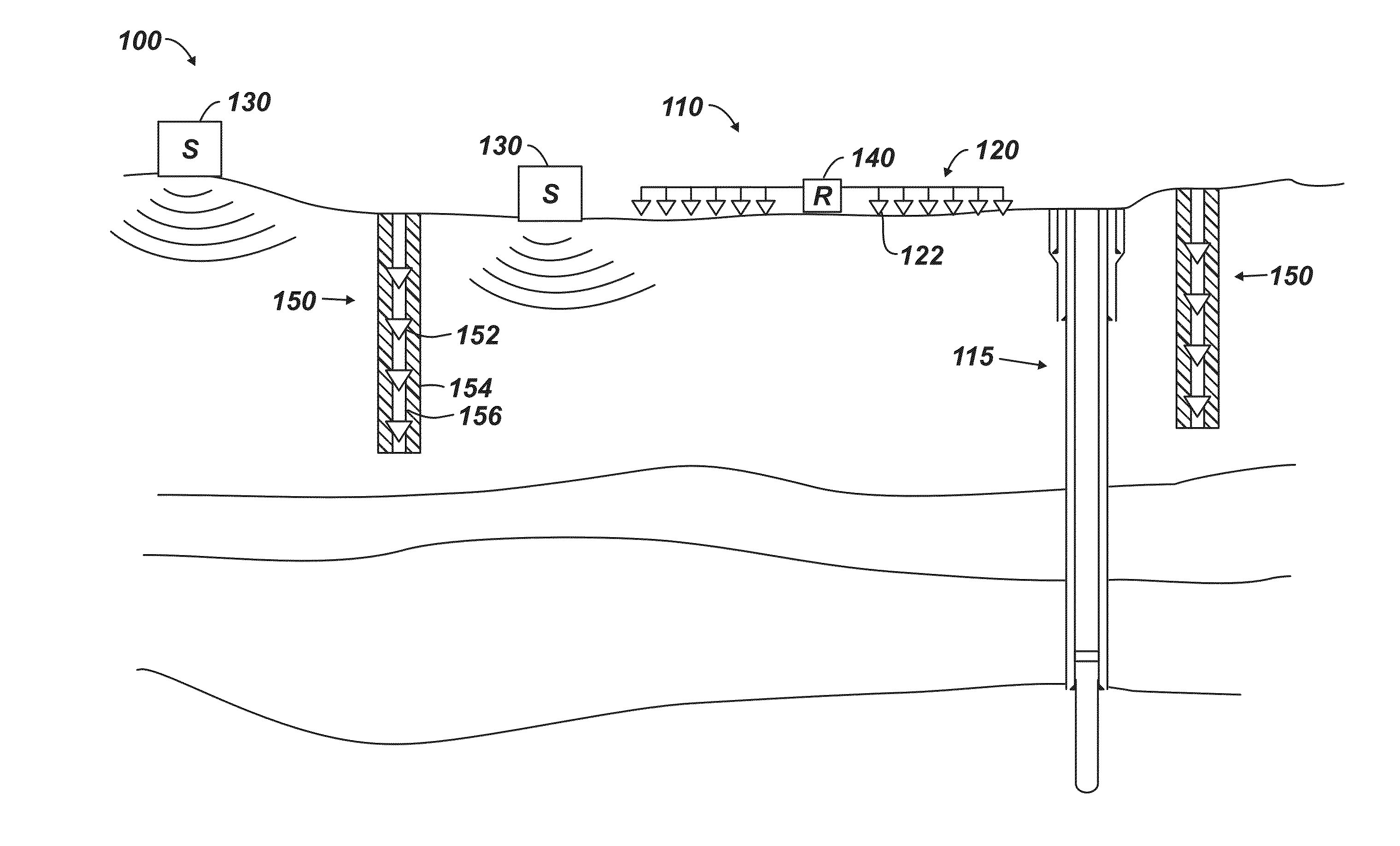
[0056]FIGS. 4A-4B schematically illustrate plan and elevational views of an integrated seismic acquisition and monitoring system 100 according to the present disclosure to generate information (e.g., geological, geomechanical, geophysical, etc.) and image earth subsurface structures of a subsurface volume or formation. Although discussed in the context of a land-based implementation, the system 100 can be used in a marine survey, as detailed later with reference to FIGS. 4E-4F.

[0057]The system 100 includes one or more sources 130, surface receivers 120 in a first arrangement relative to the formation (i.e., subsurface volume), and a recording unit 140 in communication with the surface receivers 120. In this first arrangement, the surface receivers 120 are arranged substantially horizontally in one or more arrays 110 relative to the formation (i.e., laid on the near-surface of the ground and arra...


PUM


Abstract

Microseismic mapping using buried arrays with the integration of passive and active seismic surveys provides enhanced microseismic mapping results. The system is initially set up by recording seismic data with the buried array installation while shooting a significant portion of the 3D surface seismic survey. The 3D surface seismic survey provides the following data: shallow 3D VSP data from the buried arrays; P-wave and converted wave data for the area covered by the buried array that benefits from the planned data integration processing effort; and microseismic data and associated analysis.

Description

CROSS-REFERENCE TO RELATED APPLICATIONS[0001]This is a continuation-in-part of U.S. application Ser. No. 13 / 759,986, filed 5 Feb. 2013, which is incorporated herein by reference in its entirety and which claims the benefit of U.S. Provisional Appl. 61 / 595,510, filed 6 Feb. 2012, which is also incorporated herein by reference in its entirety.BACKGROUND OF THE DISCLOSURE[0002]Land-based seismic surveying uses an array of seismic sensors deployed on the earth's surface in an area of interest. One or more seismic sources (e.g., vibrators, dynamite shots, etc.) generate seismic source signals that travel through the earth, reflect at discontinuities and other features of subsurface formations, and travel back toward the earth's surface. The seismic sensors coupled to the earth at the surface then detect the reflected source signals, and a recording unit records the detected signals. Processing of the recorded signals can then be used to image the subsurface for analysis.[0003]Land-based ...

Claims


Application Information

Patent Timeline
IPC IPC(8): G01V1/42
CPCG01V1/42G01V2210/1234G01V1/40G01V1/288
Inventor FABER, KEESLAROO, RICK
Owner NUTEC SCI
Learn More