Antenna and RF Front-end Arrangement

a technology of front-end arrangement and antenna, which is applied in the direction of diversity/multi-antenna system, independent non-interacting antenna combination, wireless communication, etc., can solve the problems of difficult to ensure the interoperability of these antennas, lte band b>7/b>, and difficult to provide sufficient isolation between the antennas, so as to reduce the number of antennas

Active Publication Date: 2013-10-10
SNAPTRACK
View PDF6 Cites 62 Cited by
  • Summary
  • Abstract
  • Description
  • Claims
  • Application Information

AI Technical Summary

Benefits of technology

[0005]In one aspect, this invention provides an antenna and RF front-end arrangement with a reduced number of antennas in a mobile phone.

Problems solved by technology

In addition to this, the more antennas a mobile phone occupies, the more difficult it will be to ensure the interoperability of these antennas.
A common challenge experienced in this implementation is the isolation between cellular and WLAN / BlueTooth antennas, where a typical target can be 10 dB of isolation between the antennas.
From a co-existence point of view, LTE band 7 is most problematic because of the close proximity of band 7 TX and RX frequencies to WLAN frequencies.
Here, it is challenging to provide sufficient isolation between the antennas.
Filtering is also difficult due to limited selectivity of filters.

Method used


Image

  • Antenna and RF Front-end Arrangement
  • Antenna and RF Front-end Arrangement
  • Antenna and RF Front-end Arrangement

Examples


first embodiment

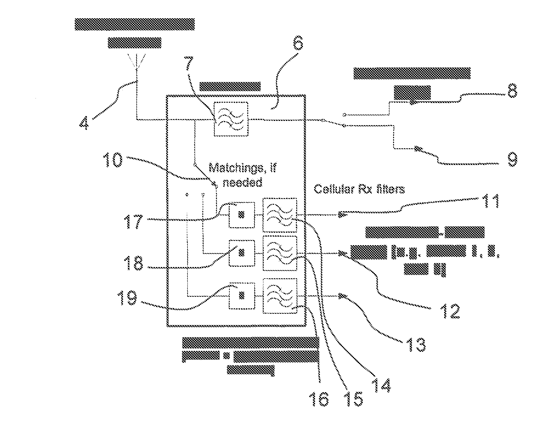
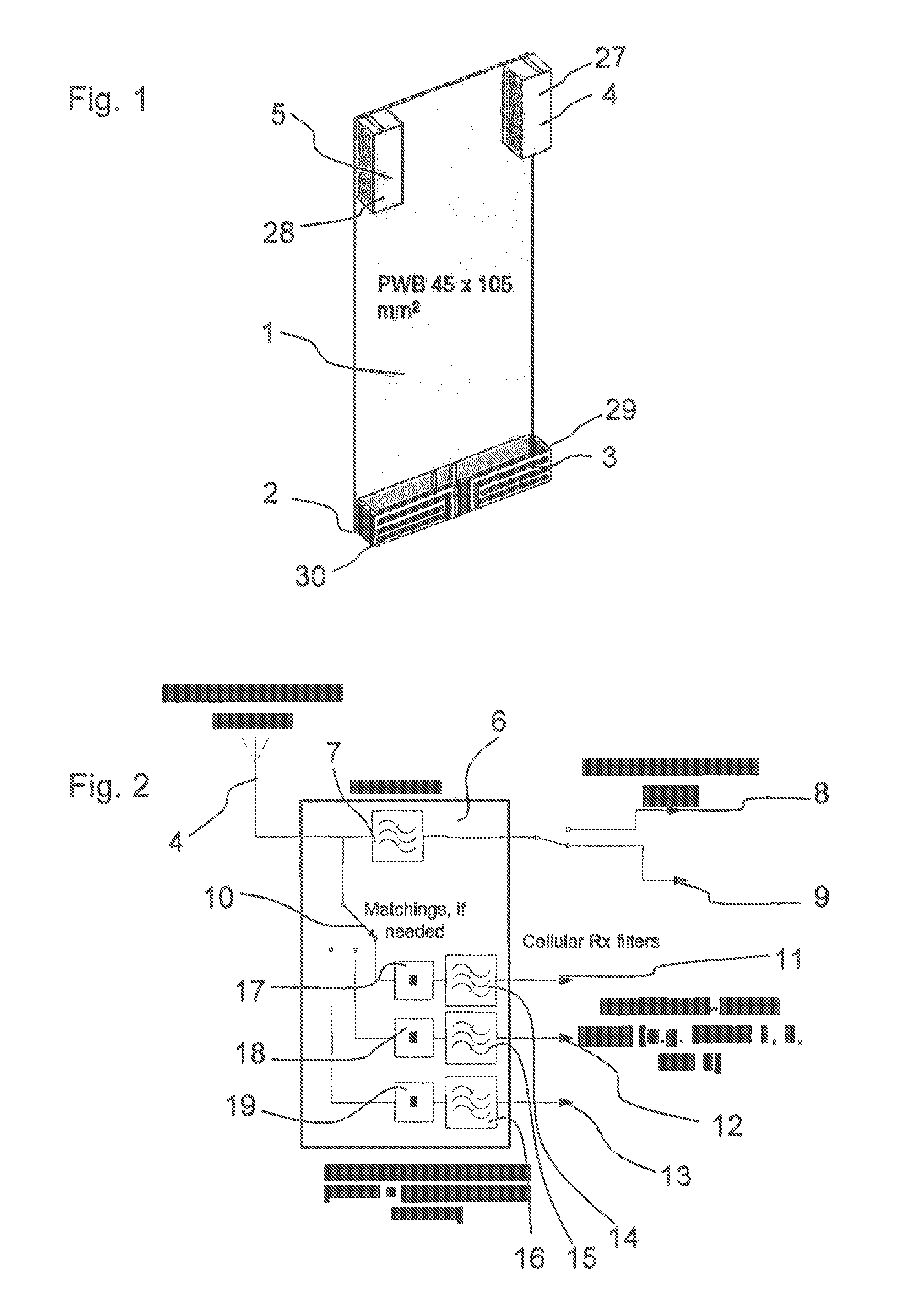
[0048]FIG. 5 shows a block diagram of a simplified example of the present invention. Here, the functionality of band 7 Rx and WLAN / BlueTooth is combined into high band MIMO Rx or diversity antenna 4. The other high band antenna 5, which is not shown in FIG. 5, is used for Tx&Rx over the respective band. As can be seen from FIG. 5, the front-end configuration simplifies with respect to FIG. 2. The switch 10 of FIG. 2 which connects the antenna 4 to different LTE or WCDMA Rx paths is not needed anymore in the embodiment of FIG. 5.

[0049]Correspondingly, if low band is used for LTE, high band MIMO Rx or diversity antenna 4 is used for sending and receiving WLAN / BlueTooth signals. Low band antennas 2, 3 are for low band LTE or WCDMA Tx and Rx paths.

second embodiment

[0050]According to the present invention, the unused MIMO Rx or diversity antenna can be used for WLAN / BlueTooth. If the high band is used for LTE, low band MIMO Rx or diversity antenna 2, 3 can be used for WLAN / BlueTooth. Respectively, if low band is used for LTE, high band MIMO Rx or diversity antenna 4, 5 can be used for WLAN / BlueTooth.

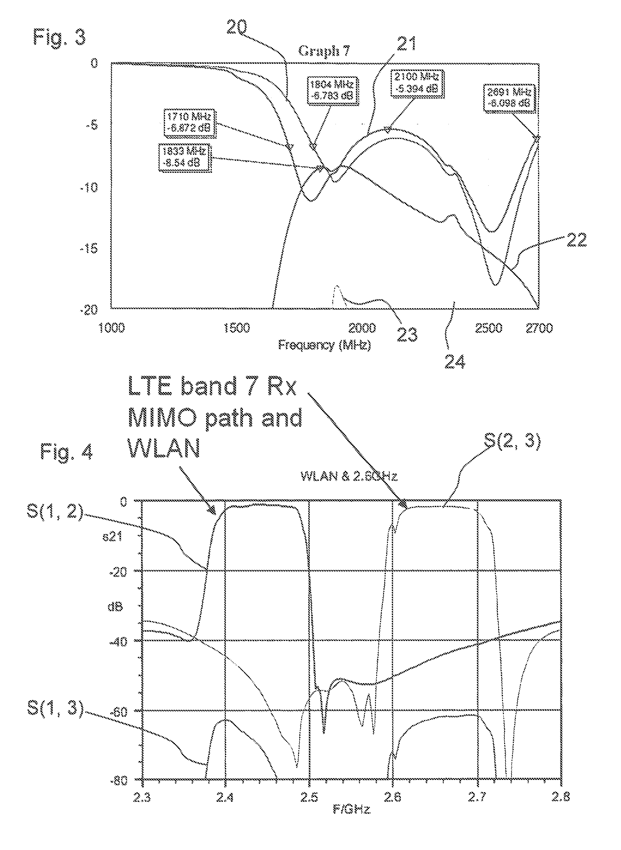
[0051]FIG. 6 shows an exemplary matching response for an embodiment where the high band antennas 4, 5 are used for LTE. Thus, they are passively matched over the entire high band. Moreover, the low band MIMO Rx or diversity antenna 2, 3 is matched over the WLAN / BlueTooth frequency with a modification in the matching circuit. In practice, the reconfigurability of the matching circuit can be handled in several ways, e.g., by switching. The first two curves 20a, 21a show the reflection coefficients for the high band antennas 4, 5. The third curve 25 shows the reflection coefficient for the low band MIMO Rx or diversity antenna 2 which is matched over ...


PUM


Abstract

An antenna and RF front-end arrangement include at least one LTE or WCDMA Tx&Rx antenna, one MIMO Rx or diversity antenna adapted for low band LTE or WCDMA and one MIMO Rx or diversity antenna adapted for high band LTE or WCDMA. At least one of the MIMO Rx or diversity antennas is adapted for transmitting and receiving WLAN and / or BlueTooth signals. Therefore, a dedicated WLAN antenna is not required and the number of antennas can be reduced.

Description

[0001]This patent application is a national phase filing under section 371 of PCT / EP2010 / 065332, filed Oct. 13, 2010, which application is hereby incorporated herein by reference in its entirety.TECHNICAL FIELD[0002]The invention concerns an antenna and radio frequency (RF) front-end arrangement comprising antennas dedicated for long-term evolution (LTE) or wideband code division multiple access (WCDMA).BACKGROUND[0003]New system protocols like LTE require additional antennas in mobile phones. In order to perform adequately, every antenna in a mobile phone requires a dedicated volume which is sufficiently free from other components. In addition to this, the more antennas a mobile phone occupies, the more difficult it will be to ensure the interoperability of these antennas. Therefore, there is a need to reduce the number of antennas in a mobile phone.[0004]Apart from the cellular antennas, a mobile phone typically comprises a variety of antennas including antennas dedicated for a wi...

Claims


Application Information

Patent Timeline
Patent Type & Authority Applications(United States)
IPC IPC(8): H04B1/44H01Q5/10
CPCH01Q1/2291H01Q1/243H01Q21/28H04B1/44H04B7/08H04W88/06H04B7/06H01Q5/10H01Q5/342
Inventor IKONEN, PEKKAELLAE, JUHA
Owner SNAPTRACK
Why Eureka
Try Eureka