
Fixing apparatus

Active Publication Date: 2013-10-10
CANON KK
View PDF1 Cites 5 Cited by
  • Summary
  • Abstract
  • Description
  • Claims
  • Application Information

AI Technical Summary

Benefits of technology

The present invention is about a fixing apparatus that can prevent uneven glossiness of an image, even when the first fixing rotatable member moves back and forth.

Problems solved by technology

Employing the configuration that causes the fixing member to reciprocate longitudinally may increase the range of deterioration of the fixing member by the edge portions of the recording material.
Thus, the increased width of the roughening roller causes more than a negligible level of warpage of the roughening roller.
If the contact pressure “b” is secured near the center of the longitudinal direction where the contact pressure is lowest, the contact pressure becomes excessively high at both ends of the rubbing area of the fixing member.
Such an excessive contact pressure applies an excessive load to the corresponding areas of the fixing member.
Repetition of the rubbing processing may cause cracking or creases in the fixing member.

Method used


Image

  • Fixing apparatus
  • Fixing apparatus
  • Fixing apparatus

Examples


Embodiment Construction

[0038]Various exemplary embodiments, features, and aspects of the invention will be described in detail below with reference to the drawings.

[0039]Various configurations of the following exemplary embodiments may be replaced with other known configurations without departing from the scope of the concept of the present disclosure unless otherwise specified.

Image Forming Apparatus

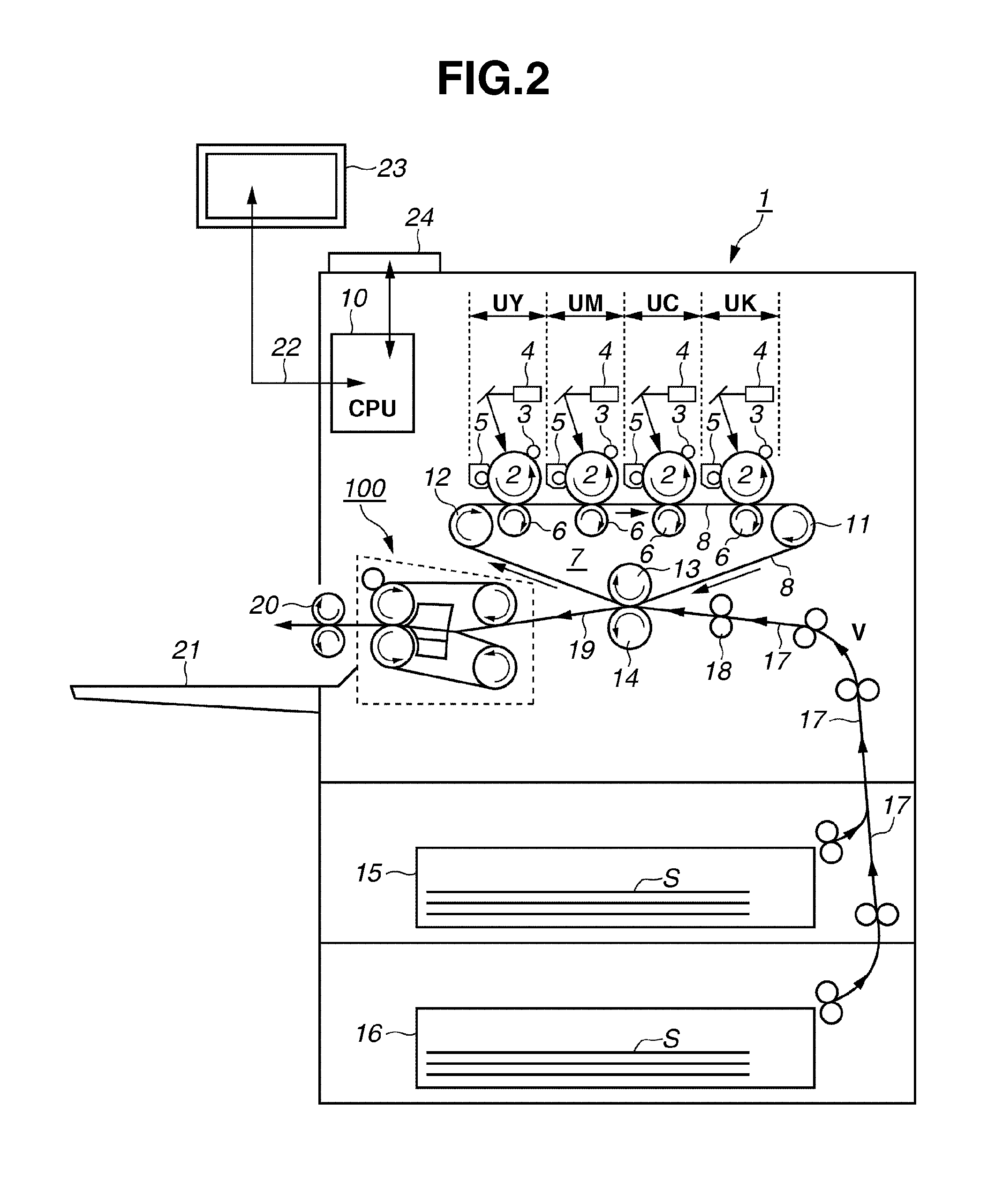
[0040]FIG. 2 is a schematic block diagram of an image forming apparatus 1 according to the present exemplary embodiment. FIG. 2 illustrates a schematic sectional view taken along a conveyance direction V of a recording material (hereinafter, referred to as a sheet) S. The image forming apparatus 1 is a four-color full color electrophotographic printer (hereinafter, referred to as a printer) of an intermediate transfer inline method. The printer 1 can form an image corresponding to image data (electrical image information) input from an external host apparatus 23 on a sheet S and outputs as an image formation ...


PUM


Abstract

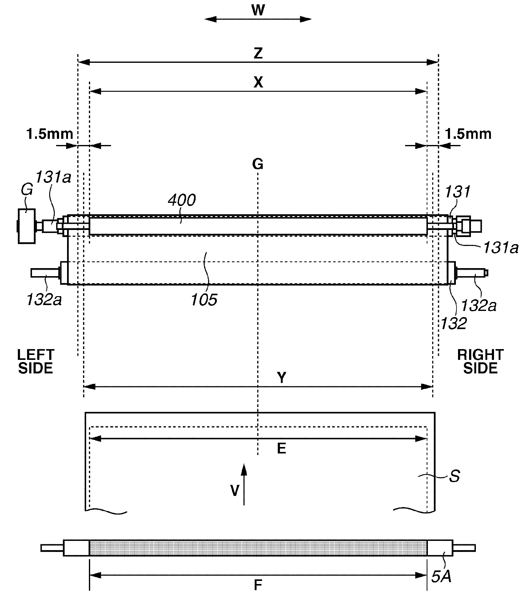
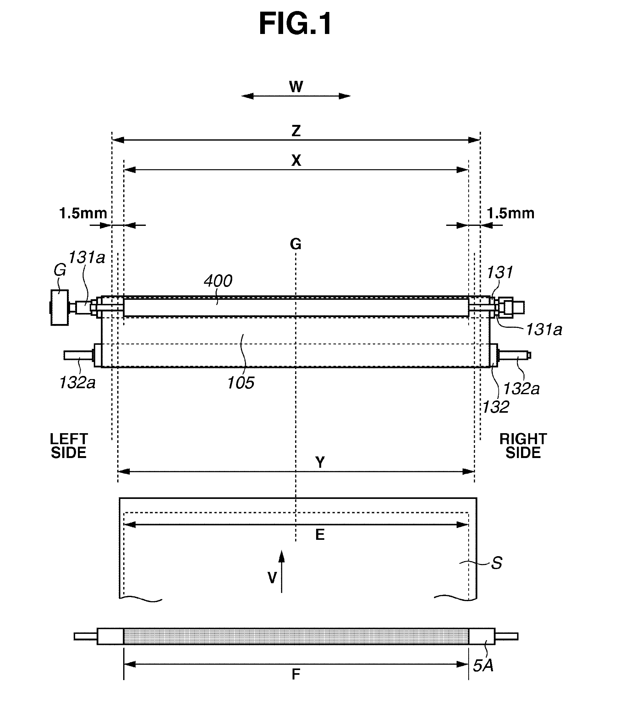
A relationship X<Y≦Z is satisfied, where X is a width of a roughening roller in a longitudinal direction, Y is a width, in the longitudinal direction, of an area where an image is able to be formed on a sheet having a maximum width usable in an apparatus, and Z is a width, in the longitudinal direction, of an area where a fixing belt is able to be rubbed by the roughening roller.

Description

BACKGROUND OF THE INVENTION[0001]1. Field of the Invention[0002]The present disclosure relates to a fixing apparatus capable of fixing a toner image on a sheet. The fixing apparatus can be used, for example, in an image forming apparatus such as a copying machine, a printer, a facsimile (FAX), and a multifunction peripheral including a plurality of such functions.[0003]2. Description of the Related Art[0004]An image forming apparatus using an electrophotographic method conventionally includes a fixing apparatus which fixes a toner image formed on a recording material (sheet) at a nip portion between two fixing members (first and second fixing rotatable members). A lot of fusibility-improved toners have recently been developed. With improved fusibility, toner can be uniformly and favorably melted by a fixing apparatus. Accordingly, the fixed toner layer is more uniformly and smoothly formed, so that image glossiness can be improved.[0005]As a result, an image having higher glossiness...

Claims


Application Information

Patent Timeline
IPC IPC(8): G03G15/20
CPCG03G15/2064
Inventor CHIKUGO, YOUICHI
Owner CANON KK
Learn More