Method and system for controlling a secondary flow system

a secondary flow and control method technology, applied in the direction of engines, machines/engines, mechanical equipment, etc., can solve the problems of undesirable emissions and/or pollutants in the combustion process

Inactive Publication Date: 2013-10-17
GENERAL ELECTRIC CO
View PDF24 Cites 84 Cited by
  • Summary
  • Abstract
  • Description
  • Claims
  • Application Information

AI Technical Summary

Benefits of technology

[0008]In accordance with a first embodiment of the present invention, a system comprising: an oxidant compressor comprising an ac_inlet and an ac_outlet; a compressor comprising a compressor inlet and a compressor outlet; wherein the compressor operates independently of the oxidant compressor; at least one combustion system that operatively generates a working fluid and comprises a head end and a discharge end, wherein the at least one combustion system is fluidly connected to: the ac_outlet, the compressor outlet, and a first fuel supply; a first turbine section operatively connected to the compressor, wherein the turbine section comprises a PT_inlet which receives the working fluid from the at least one combustion system, a PT_outlet that discharges the working fluid; and at least one secondary flow circuit; an exhaust section fluidly connected to the PT_outlet; an exhaust gas recirculation (EGR) system fluidly connected between a discharge of the exhaust section and the compressor inlet such that the working fluid exiting the exhaust section is ingested by the compressor inlet; wherein the EGR system comprises a control device for adjusting a physical property of the working fluid; an extraction that removes a portion of the working fluid; and a secondary fluid source fluidly connected to the at least one secondary flow circuit, wherein the secondary fluid source supplies a substantially oxygen free fluid to the at least one secondary flow circuit.

Problems solved by technology

The combustion process creates undesirable emissions and / or pollutants, such as Carbon Monoxide (CO) and Oxides of Nitrogen (NOx).

Method used


Image

  • Method and system for controlling a secondary flow system
  • Method and system for controlling a secondary flow system
  • Method and system for controlling a secondary flow system

Examples


first embodiment

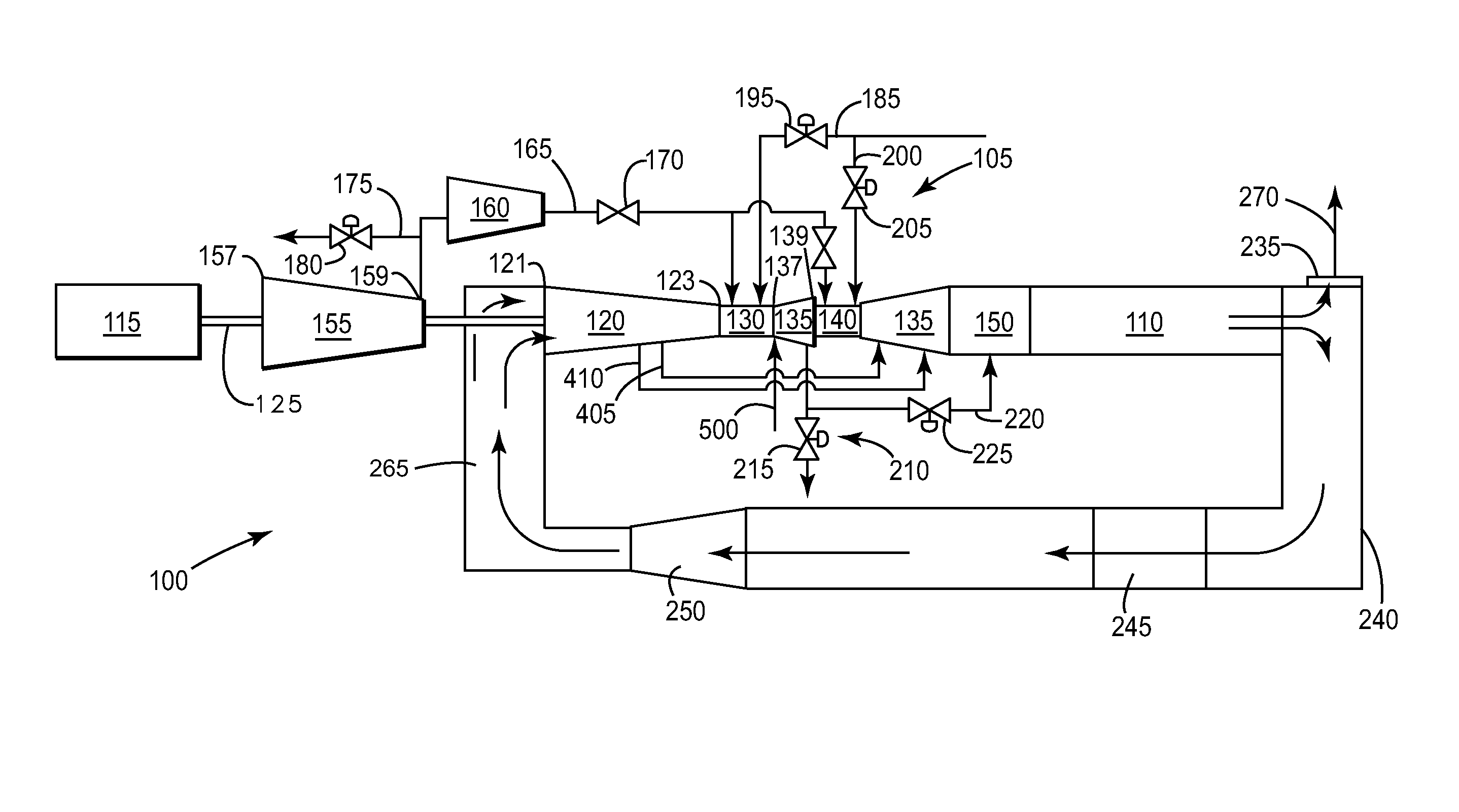
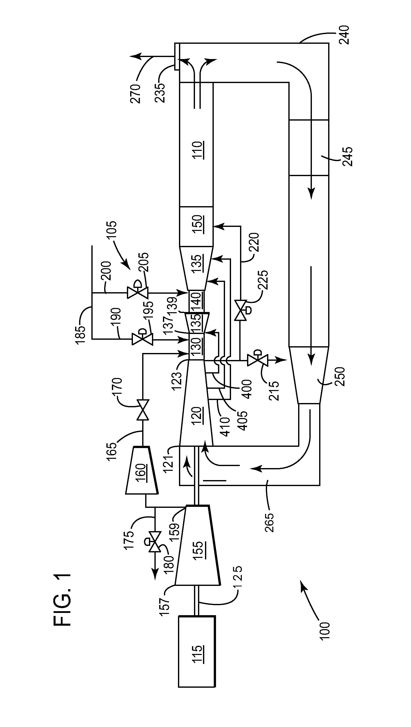
[0031]As illustrated in FIGS. 1 and 2, embodiments of the present invention may position the extraction 210 at various locations of the gas turbine 105. The location of the extraction 210 may be a factor in determining whether the primary combustion system 130 or the secondary combustion system 140, is operated in a stoichiometric manner. As illustrated in FIG. 1, the present invention positions the extraction 210 adjacent a discharge of the GT compressor 120. The working fluid within the GT compressor 120 may be used as the cooling fluid for both the primary turbine section 135 and the secondary turbine section 145, as illustrated in FIG. 1. Here, the primary combustion system 130 may not be operating in stoichiometric mode, unlike the secondary combustion system 140.

second embodiment

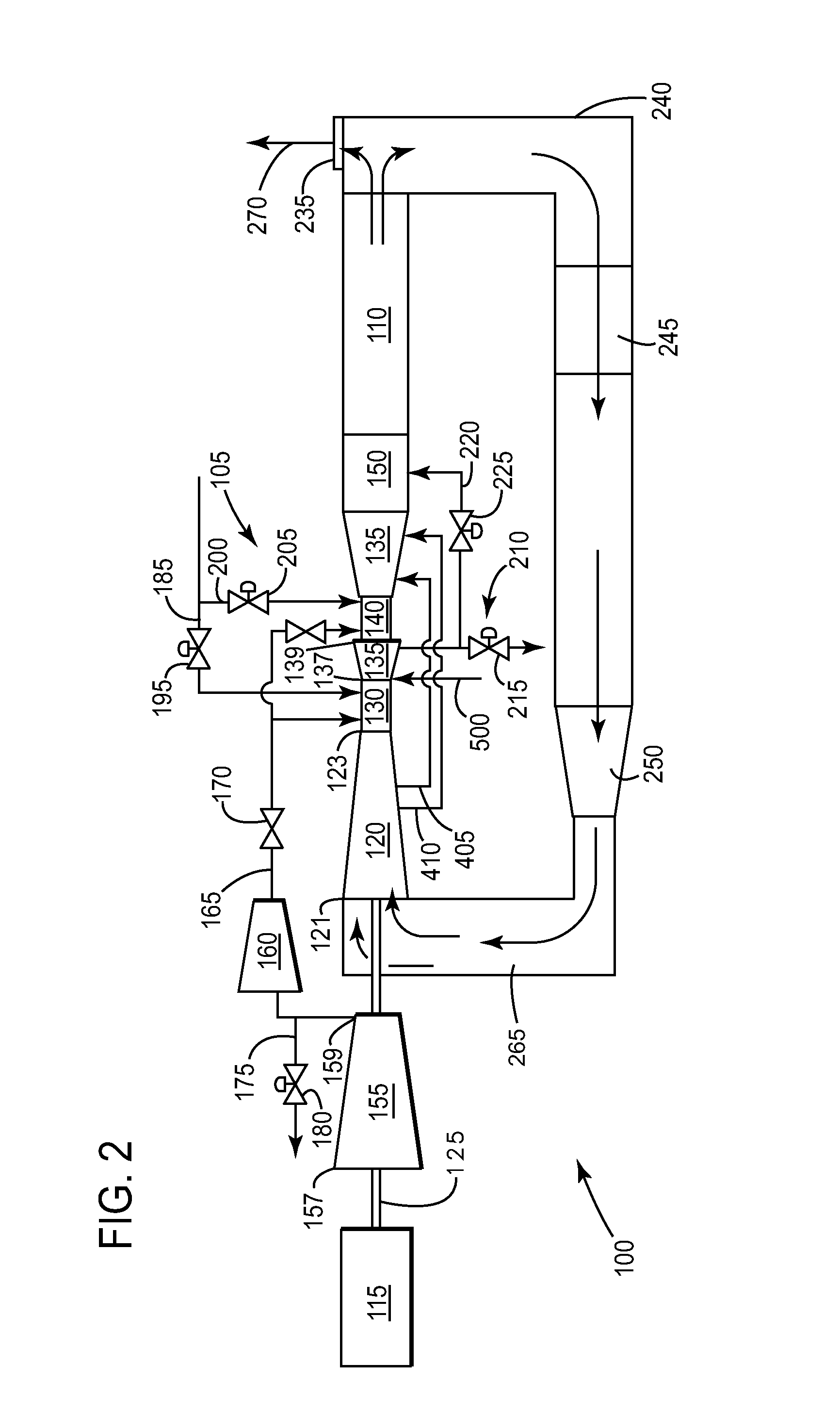
[0032]The above discussion, in relation to FIG. 1, describes the basic concept of a reheat gas turbine 105 configured for S-EGR operation. For convenience, components and elements that correspond to those identified in FIG. 1 are identified with similar reference numerals in FIG. 2, but are only discussed in particular, as necessary, or desirable, to an understanding of the

[0033]FIG. 2 is a simplified schematic of a reheat gas turbine operating in a closed-cycle mode, illustrating a second embodiment of the present invention. The primary difference between the reheat gas turbine 105 in FIG. 2 and FIG. 1 is the location of the extraction 210. In this second embodiment, the extraction 210 is located at a discharge of the primary turbine 135 (as illustrated in FIG. 2). In this configuration the primary combustion system 130 may operate in stoichiometric manner, and the secondary combustion system 140 may not operate in a stoichiometric manner. This may result in the working fluid in th...


PUM


Abstract

Embodiments of the present invention provide to a cooling and sealing air system for reheat gas turbine powerplant operating in a configuration that includes stoichiometric exhaust gas recirculation configuration. A user may have the flexibility in determining where the cooling and sealing flow derives. This may include and enhanced oil recovery system, a concentrated carbon system, etc.

Description

BACKGROUND OF THE INVENTION[0001]This application is related to [GE Docket 249101], [GE Docket 249104], [GE Docket 250883], [GE Docket 250884], [GE Docket 250998], [GE Docket 256159], [GE Docket 257411], and [GE Docket 258552] filed concurrently herewith, which are fully incorporated by reference herein and made a part hereof[0002]The present application relates generally to a combined-cycle powerplant; and more particularly to a system and method for operating a turbomachine incorporated with stoichiometric exhaust gas recirculation (S-EGR).[0003]In an air-ingesting turbomachine, compressed air and fuel are mixed and combusted to produce a high energy fluid (hereinafter “working fluid”) that is directed to a turbine section. The working fluid interacts with turbine buckets to generate mechanical energy, which is transferred to a load. In particular, the turbine buckets rotate a shaft coupled to the load, such as an electrical generator. The shaft rotation induces current in a coil ...

Claims


Application Information

Patent Timeline
Patent Type & Authority Applications(United States)
IPC IPC(8): F02C3/34F02C7/228F02C3/04
CPCF02C3/34F02C7/12F02C9/18Y02E20/16
Inventor WICHMANN, LISA ANNESIMPSON, STANLEY FRANK
Owner GENERAL ELECTRIC CO
Why Eureka
Try Eureka