Sensing device and method of attaching the same

a technology of sensing device and sensor, which is applied in the direction of instruments, chemistry apparatus and processes, and solids analysis using sonic/ultrasonic/infrasonic waves, etc., can solve the problems of delamination of bonding material to pipe formed by bonding material, failure of bonding line formation, and delamination of bonding material, so as to improve the resistance to bond failure and delamination. , the effect of improving the formation of bond lines

Active Publication Date: 2013-10-17
BAKER HUGHES INC
View PDF9 Cites 0 Cited by
  • Summary
  • Abstract
  • Description
  • Claims
  • Application Information

AI Technical Summary

Benefits of technology

[0006]A sensing device and a method of attaching the sensing device to a target object is disclosed. The substrate of the sensing device has a one or more bonding material vias that allows the bonding material used to attach the substrate to the target object to flow from one side of the substrate to the other side of the substrate. The bonding material...

Problems solved by technology

In some installations, when the piezoelectric sensing device is attached to the pipe, the bond line formed by the bonding material is too thick, degrading the performance of the piezoelectric sensing device.
The bond to the pipe formed by the bonding material, ...

Method used


Image

  • Sensing device and method of attaching the same
  • Sensing device and method of attaching the same
  • Sensing device and method of attaching the same

Examples


Embodiment Construction

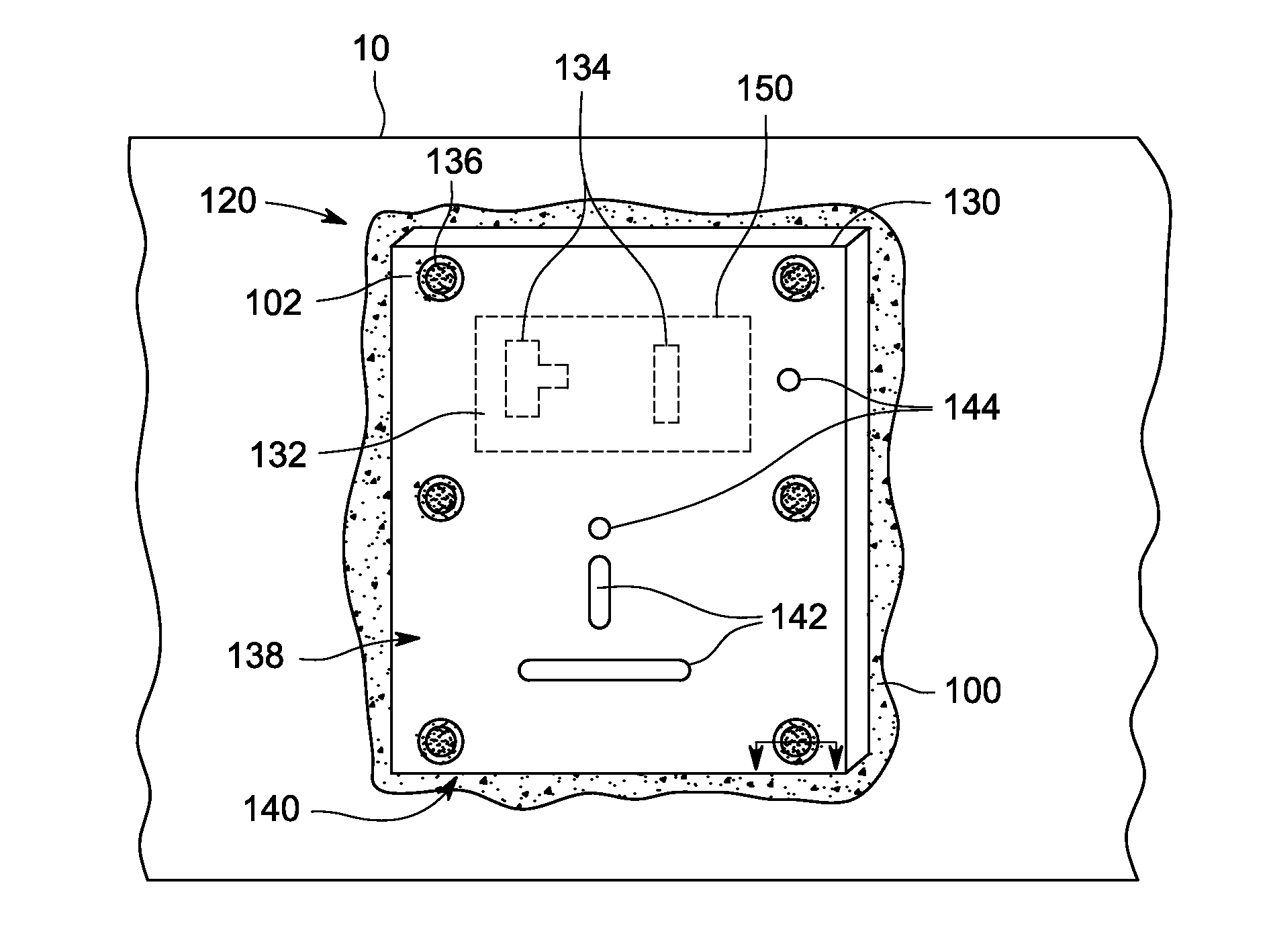
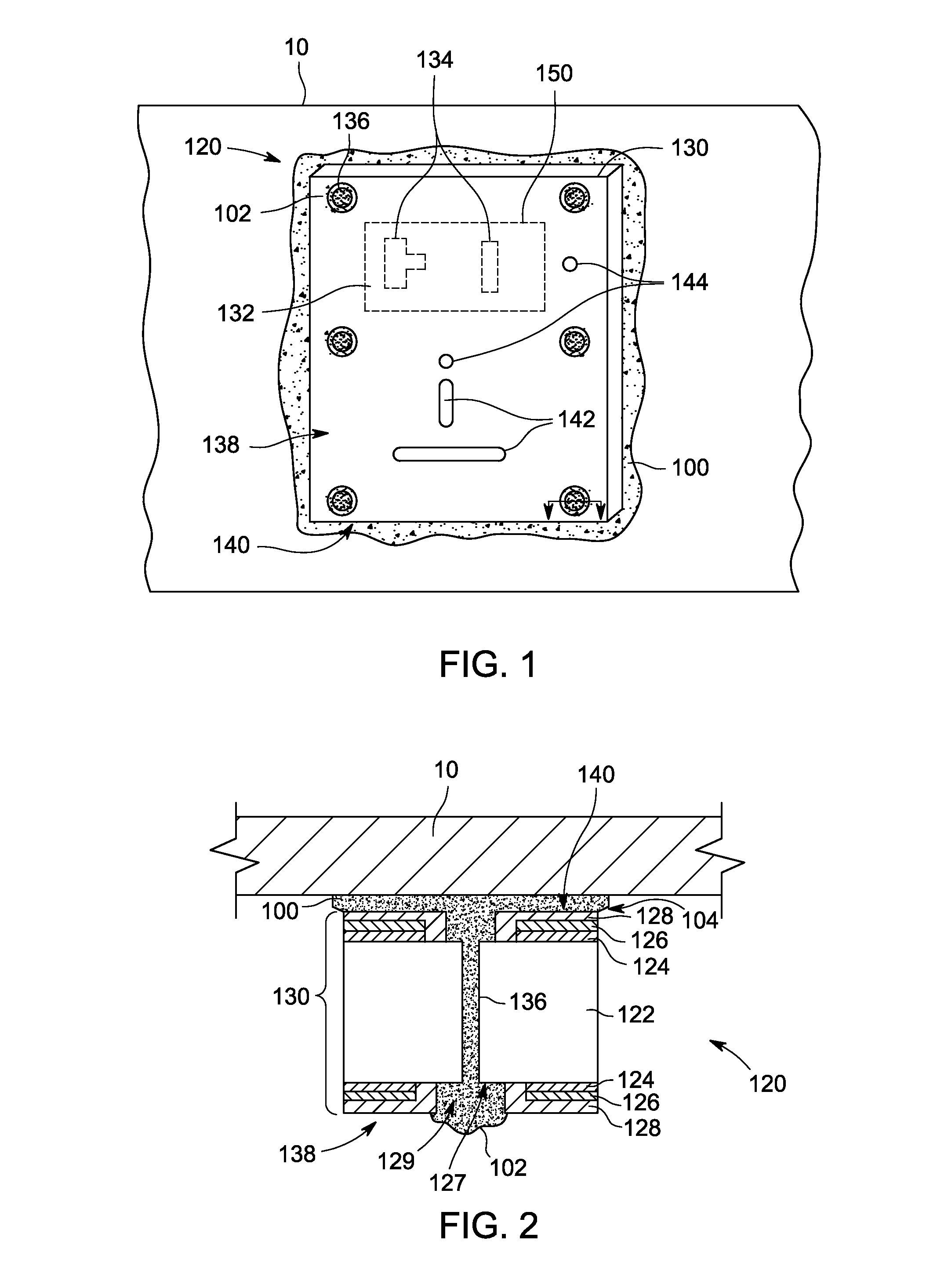
[0016]Referring now to the figures, FIG. 1 is a schematic diagram of an exemplary embodiment of a sensing device 120 affixed to a target object 10 with bonding material 100. FIG. 2 is a cross-sectional view of an exemplary bonding material via 136 of the substrate 130 of the sensing device 120 shown in FIG. 1. As will be explained, the bonding material 100 flows through one or more bonding material vias 136 in the sensing device 120 to form bonding rivets 102. Once cured, the bonding rivets 102 help to prevent the substrate 130 of the sensing device 120 from delaminating or from peeling off the target object 10.

[0017]As shown in FIG. 1, the sensing device 120 is disposed on the target object 10, such as a pipe, a tube, or related conduits that can be subject to corrosion and erosion by way of the fluid that is transported therein. In one embodiment, the sensing device 120 is part of an ultrasonic inspection system and includes a sensing element in the form of a piezoelectric element...


PUM

PropertyMeasurementUnit
Pressureaaaaaaaaaa
Flexibilityaaaaaaaaaa
Piezoelectricityaaaaaaaaaa

Abstract

A sensing device and a method of attaching the sensing device to a target object is disclosed. The substrate of the sensing device has one or more bonding material vias that allows the bonding material used to attach the substrate to the target object to flow from one side of the substrate to the other side of the substrate. The bonding material forms rivets to secure the substrate to the target object and to secure the layers of the substrate to each other.

Description

BACKGROUND OF THE INVENTION[0001]The subject matter disclosed herein relates to a sensing device attached to a target object using a bonding material.[0002]Several industries (e.g., oil and gas, refinery, chemical, power generation) require the transport of fluid (e.g., liquids or gases) through pipes. Nondestructive testing systems can be placed on the outer surface of these pipes to monitor corrosion / erosion of the pipes, including corrosion / erosion on the interior of pipe walls. In some nondestructive testing systems, the probe or other nondestructive testing device is permanently coupled to the outer surface of the pipe to continuously monitor corrosion / erosion at that location to determine pipe corrosion / erosion rates and to determine whether that pipe location is in need of preventative maintenance to prevent a pipe failure.[0003]One example of a nondestructive testing system used to monitor corrosion / erosion of a pipe is an ultrasonic testing system. When conducting ultrasoni...

Claims


Application Information

Patent Timeline
IPC IPC(8): G01N29/04B32B37/12
CPCG01N29/223G01N29/245G01N2291/2634
Inventor KROHN, MATTHEW HARVEYMEYER, PAUL ALOYSIUSSMITH, NATHAN JOHNMATTHEWS, FRED TIMOTHY
Owner BAKER HUGHES INC
Why Eureka
Try Eureka