
Laminated optical products and methods of making them

a technology of laminated optical products and manufacturing methods, applied in the direction of instruments, synthetic resin layered products, optical elements, etc., can solve the problems of mechanical and chemical challenges, environmental hazards and costs, and the film and its manufacturing process suffer various drawbacks, so as to improve the resistance to delamination during storage and use.

Pending Publication Date: 2019-03-21
SOUTHWALL TECH INC
View PDF2 Cites 1 Cited by
  • Summary
  • Abstract
  • Description
  • Claims
  • Application Information

AI Technical Summary

Benefits of technology

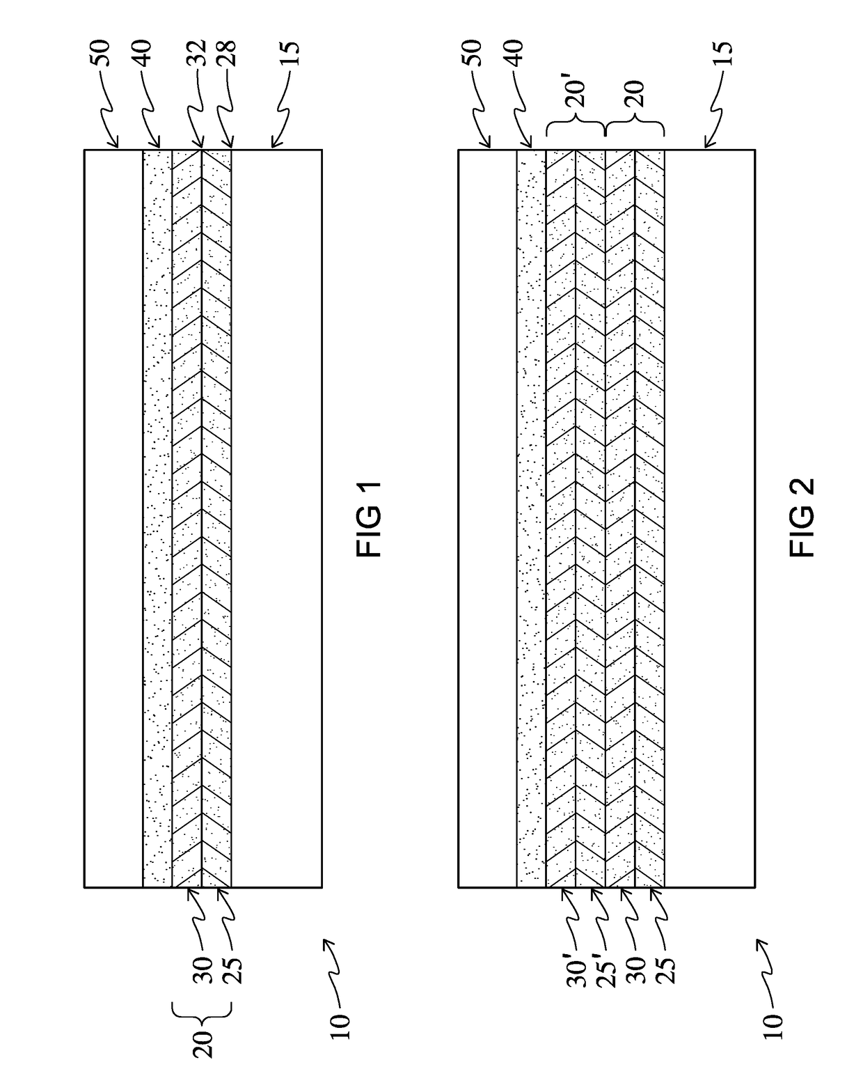
The present patent is about new optical products made from a polymer material that has a layer of composite coating. This coating is applied to the polymer substrate and includes two layers that have a binding group that matches up to form a complementary pair. The new optical products have improved resistance to delamination during storage and use.

Problems solved by technology

These films and their manufacturing processes suffer various drawbacks.
For example, the substrates require exposure to organic solvents and elevated temperatures, which present both mechanical and chemical challenges such as environmental hazards and costs associated with storing the raw solvents and disposing of the resulting waste.
Also, only a limited number of organic dyes are soluble and stable in the hot solvent and many of them are subject to degradation by the high-energy radiation (sub 400 nm wavelength) to which the film is subjected, thereby shortening the useful lifetime of the product.
Further, uneven rates of degradation for the several dyes used can result in a color shift over the lifetime of the film.
One drawback of these metal layers is that they also block other unintended portions of the EM spectrum including RF and microwave frequencies, interfering with cell phone and radio signals, as well as rain sensors in automobiles.
These films are typically porous, and more susceptible to delamination than more conventional window film components such as those already described.
These layer-by-layer films are thus prone to wear and are typically provided with a hardcoat, a protective polymer layer, or both.

Method used


Image

  • Laminated optical products and methods of making them

Examples


examples

[0058]In a first set of examples, an LbL coated substrate was used in which the PET substrate had deposited on it alternating layers of polyallylamine hydrochloride (PAH) polymer and a pigment combination that included carbon black Cab-o-jet 352K, cyan Cab-o-jet 250C, and magenta Cab-o-jet 265M, all from Cabot Corporation. A total of 25 bilayers were deposited. Two different adhesives, a PSA (a self-cross-linking solution acylic Duro-Tak 109A from Henkel) and a conventional laminating adhesive (Adcote 76R36 (Dow), an aliphatic polyester polyol formulated with an isocyanate cross-linker), were each applied via gravure roller to separate 3 mil PET substrates and each substrate was then passed through a drying oven in which the solvent was evaporated. The adhesive-coated PET films were each then hot nipped to a previously coated Layer-by-Layer film, at 180° F. and 4 bar nip pressure at a 10 fpm line speed.

[0059]A bag delamination test was performed on these examples to test the adhesiv...


PUM

PropertyMeasurementUnit
Fractionaaaaaaaaaa
Thicknessaaaaaaaaaa
Thicknessaaaaaaaaaa

Abstract

Optical products are disclosed that include a polymer substrate; a composite coating, deposited on the polymer substrate; a permeating adhesive, which permeates the composite coating and is in contact with the polymer substrate; and a protective layer, secured to the composite coating by the permeating adhesive. The composite coating includes at least a first layer and a second layer, each of which is provided with a binding group component which together form a complementary binding group pair. The optical products exhibit improved resistance to delamination during storage and use.

Description

FIELD OF THE INVENTION[0001]The present invention relates to laminated optical products that include a polymer substrate, a layer-by-layer composite film deposited on the substrate, and a protective layer laminated to the layer-by-layer composite film with a permeating adhesive that provides resistance to delamination.BACKGROUND OF THE INVENTION[0002]Modern heat rejection films are typically multilayer films applied to glass or plastic windows to reduce the amount of infrared (IR), visible light, ultraviolet (UV), and / or other electromagnetic (EM) radiation entering windows. These films are designed to allow only desirable portions of the incoming solar spectrum to penetrate the window.[0003]Early solar control films included dyed polymeric substrates, in which color was imparted through the use of organic dyes. These films and their manufacturing processes suffer various drawbacks. For example, the substrates require exposure to organic solvents and elevated temperatures, which pre...

Claims


Application Information

Patent Timeline
IPC IPC(8): G02B5/22G02B1/14B32B7/12B32B37/12B32B27/08B32B27/20
CPCG02B5/223G02B1/14B32B7/12B32B37/12B32B27/08B32B27/20B32B2307/40B32B2255/00B32B2309/105B32B27/00G02B5/208G02B1/00
Inventor KROGMAN, KEVIN C.BOMAN, LEE CAMPBELLKOZAK, JULIUS GEORGEPATEL, KAYUR ASHWINSTEGALL, JEREMY B.PORT, ANTHONY BRIAN
Owner SOUTHWALL TECH INC
Learn More