Ratchet Wrench Capable of Being Operated Through Relatively Smaller Minimum Swing Angle Action

a technology of ratchet wrenches and minimum swing angles, which is applied in the field of ratchet wrenches, can solve the problems of compact wrenches that cannot withstand large torque transmission, and achieve the effect of reducing the minimum swing angle and withstanding torque transmission

Active Publication Date: 2013-10-17
CHANG CHIH MIN
View PDF4 Cites 19 Cited by
  • Summary
  • Abstract
  • Description
  • Claims
  • Application Information

AI Technical Summary

Benefits of technology

[0011]It is therefore an objective of the present invention to provide a ratchet wrench which better withstands torque transmission and is capable of being operated through a relatively smaller minimum swing angle action.

Problems solved by technology

However, the compact wrench can not withstand large torque transmission.

Method used


Image

  • Ratchet Wrench Capable of Being Operated Through Relatively Smaller Minimum Swing Angle Action
  • Ratchet Wrench Capable of Being Operated Through Relatively Smaller Minimum Swing Angle Action
  • Ratchet Wrench Capable of Being Operated Through Relatively Smaller Minimum Swing Angle Action

Examples


Embodiment Construction

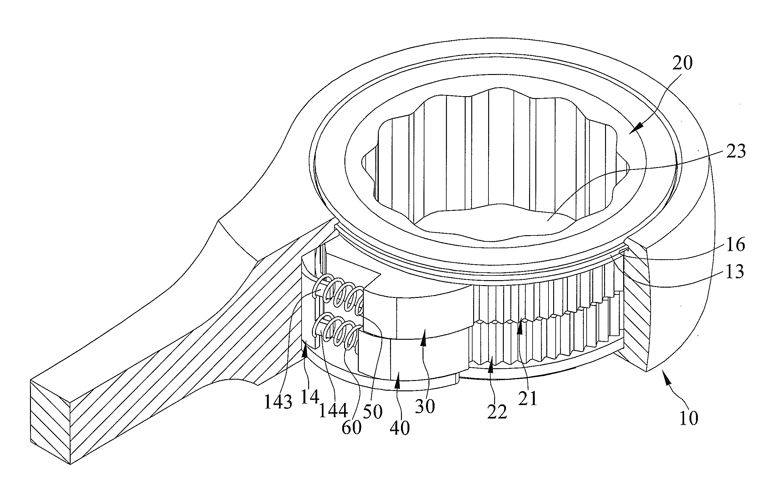
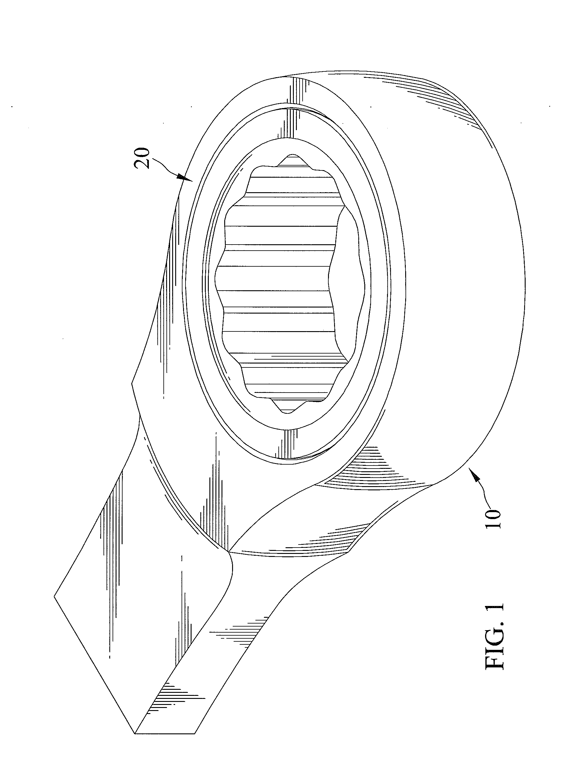
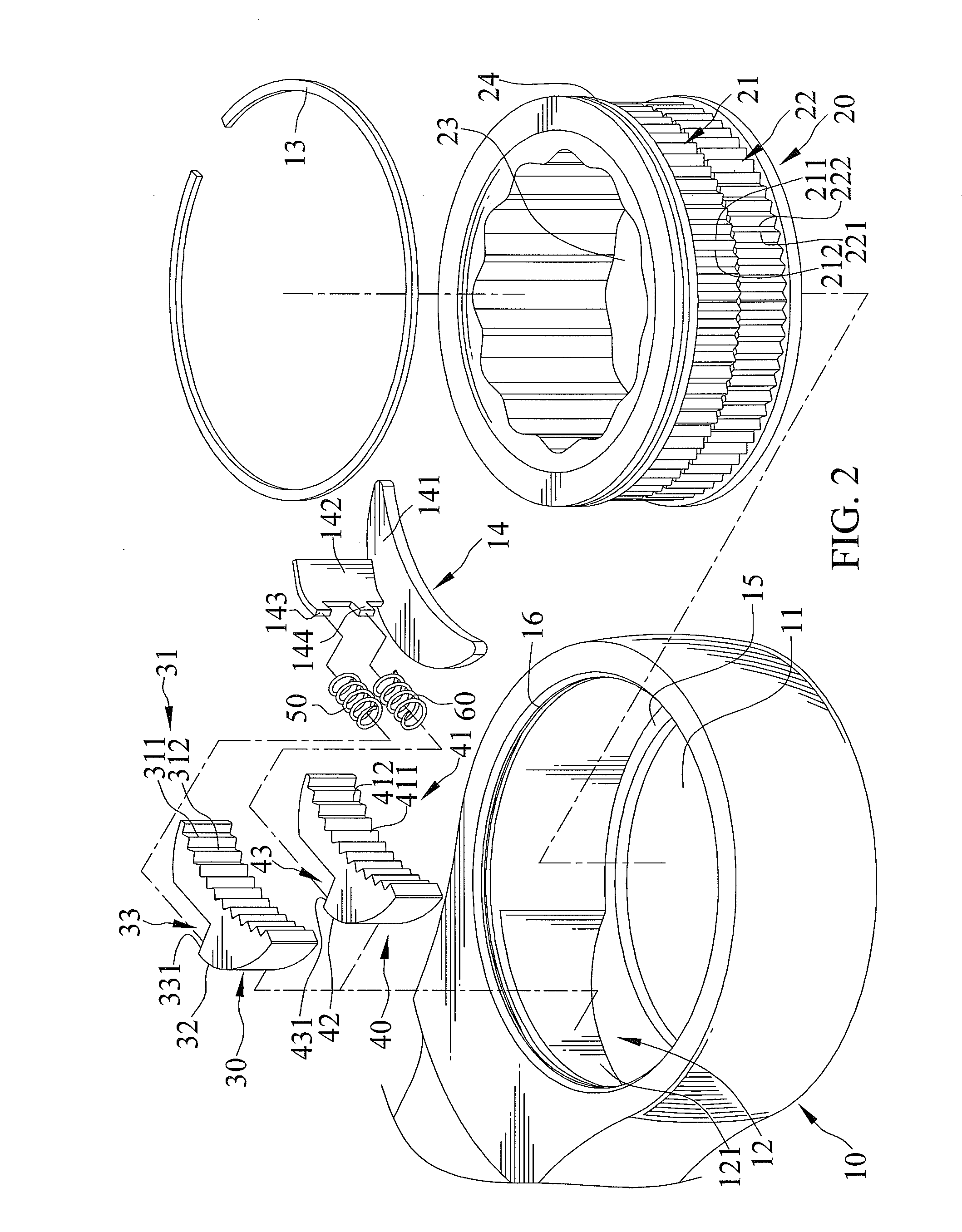
[0031]FIGS. 1 through 8 show a ratchet wrench capable of being operated through a relatively smaller minimum swing angel action in accordance with a first embodiment of the present invention. The adjustable wrench includes a head 10. The head 10 includes a chamber defined therein, and a gear wheel 20, a first pawl 30, and a second pawl 40 are disposed in the chamber. The chamber defines first and second compartments 11 and 12. The gear wheel 20 is disposed in the first compartment 11. A flange 15 is extended circumferentially from a wall delimiting the first compartment 11 for bearing the gear wheel 20. A groove 16 is extended circumferentially from the first compartment 11. The gear wheel 20 has an outer periphery thereof including a channel 24 circumferentially inset therein. An annular clip 13 is partially engaged in the groove 16 and partially in the channel 24 to lock the gear wheel 20 to the head 10. The first and second pawls 30 and 40 are disposed in the second compartment 1...


PUM


Abstract

A ratchet wrench includes a head. A gear wheel, a first pawl, and a second pawl are disposed in a chamber defined in the head. The gear wheel has an outer periphery thereof including a plurality of teeth extended circumferentially outwardly therefrom. The first and second pawls each include a lateral side thereof including third and fourth plurality of teeth respectively extended outwardly therefrom. The first and second pawls are disposed one above the other. The first and second pawls are respectively biased by first and second biasing mechanisms. The first and second pawls are alternatively engaged with the gear wheel when it is operably turned.

Description

BACKGROUND OF THE INVENTION[0001]1. Field of the Invention[0002]The present invention relates to a ratchet wrench and, in particular, to a ratchet wrench which better withstands torque transmission and is capable of being operated through a relatively smaller minimum swing angle action.[0003]2. Description of the Related Art[0004]TW Patent No. M423025 shows a wrench including a pawl and a gear wheel, and designs of the pawl and the gear wheel determine the minimum swing angle that the wrench can be turned to wrench an object. The pawl includes a side thereof including a plurality of teeth. The gear wheel is rotatable with respect to an axis and includes an annular outer periphery including a plurality of teeth. The teeth of the pawl is clutched with a portion of the plurality of teeth of the gear wheel and the gear wheel is prevented from rotation when the object is turned by the wrench, and the gear wheel is rotated relative to the pawl and includes the teeth movably engaging with ...

Claims


Application Information

Patent Timeline
Patent Type & Authority Applications(United States)
IPC IPC(8): B25B13/46
CPCB25B13/463B25B13/481
Inventor HUANG, PING-WEN
Owner CHANG CHIH MIN
Why Eureka
Try Eureka