Internally cooled billet guiding roller

a guiding roller and billet technology, applied in the direction of manufacturing tools, lighting and heating equipment,foundry moulding apparatus, etc., can solve the problem that the central shaft remains as far as possible unaffected, and achieve the effect of quick dissipation of heat quantities, improved mechanical and thermal resistance, and increased maintenance ease of the guiding roll

Active Publication Date: 2008-02-05
PRIMETALS TECH AUSTRIA GMBH
View PDF8 Cites 13 Cited by
  • Summary
  • Abstract
  • Description
  • Claims
  • Application Information

AI Technical Summary

Benefits of technology

[0013]Therefore, it is an object of the present invention to avoid the drawbacks of the known prior art and to propose a strand-guiding roll with internal cooling which quickly dissipates the heat quantities taken up by the roll shell and is better able to withstand the mechanical and thermal stresses caused by the strand. In particular, it is intended for it to be possible to increase the ease of maintenance of the strand-guiding roll and to carry out maintenance work more cost-effectively. A further object of the invention is to provide a strand-guiding roll which is suitable even for large cast widths and is structured in such a way that maintenance work can be restricted to replacing components that are susceptible to wear.
[0015]To simplify production of the coolant passages in the roll shell, the roll shell may comprise two annular sleeves which are rotationally fixedly connected to one another, and the coolant passages, at the connecting lateral surfaces of the two annular sleeves, are machined into at least one of these connecting lateral surfaces. The two annular sleeves of the roll shell may be connected, for example, by a shrink-fit connection or by end-side welding.
[0016]According to another expedient embodiment, it is likewise possible for the coolant passages to be moved as close as possible to the roll shell outer surface, by virtue of the fact that the roll shell comprises at least one outer sleeve, which forms the roll shell outer surface, annular side parts and a displacement body, and this displacement body is inserted in a cavity in the roll shell extending between the annular side parts, the displacement body, together with the inner wall of the outer sleeve, forming coolant passages for a coolant to pass through. The displacement body, which is preferably made from a plastic, makes it simple to form coolant passages which are configured and routed in any desired way. The cross sections of the coolant passages may also adopt the shape of ring segments or may be reduced to a single annular coolant passage.
[0017]According to a preferred embodiment of the invention, at least one water guide ring is arranged between the roll shell and the central shaft. According to an expedient embodiment, the water guide ring is arranged in the end regions of the longitudinal extent of the roll shell, between the roll shell and the central shaft. Designing the water guide rings as independent components and arranging them in the edge regions of each roll shell results in functional separation between the components. The water guide ring is used exclusively to supply coolant to the coolant passages, and its internal diameter and external diameter are dimensioned in such a way that as far as possible no reaction forces from the strand and also no driving forces from the roll drives act on it and are transmitted via it. At the same time, suitable steps in the shaft diameter at the contact surfaces with the water guide rings result in simple assembly and dismantling of the strand-guiding roll for maintenance work and allow a roll shell to be replaced.

Problems solved by technology

Therefore, the central shaft remains as far as possible unaffected by the thermal stressing of the roll shell.

Method used


Image

  • Internally cooled billet guiding roller
  • Internally cooled billet guiding roller
  • Internally cooled billet guiding roller

Examples


Embodiment Construction

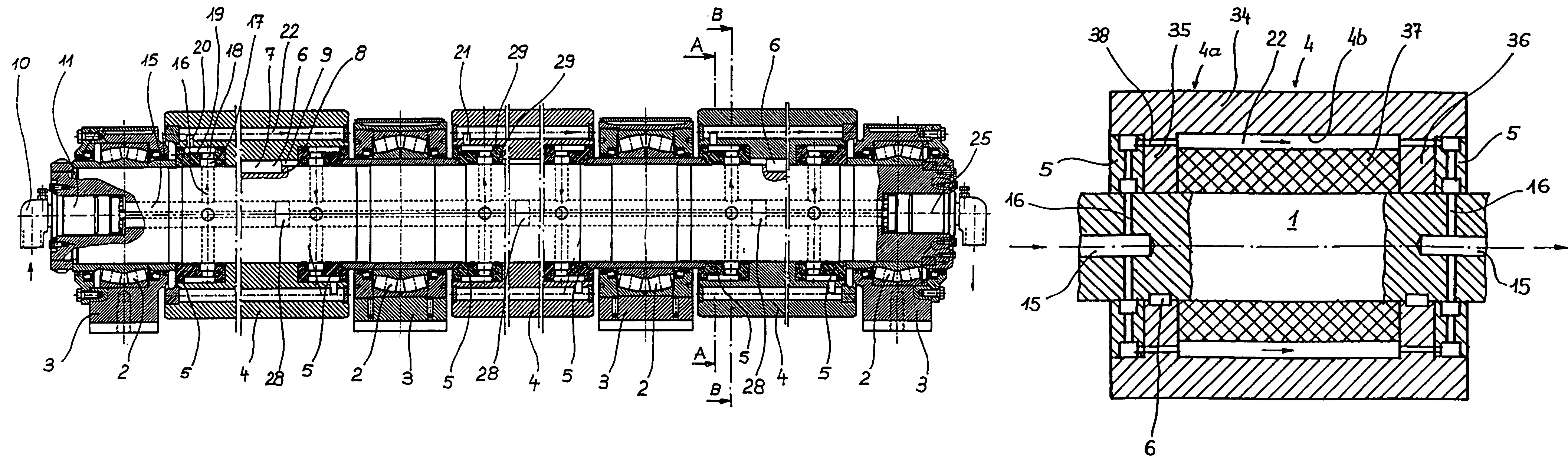
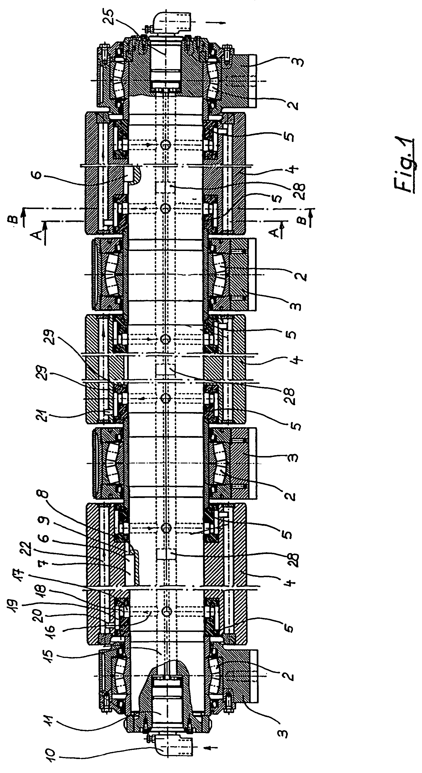
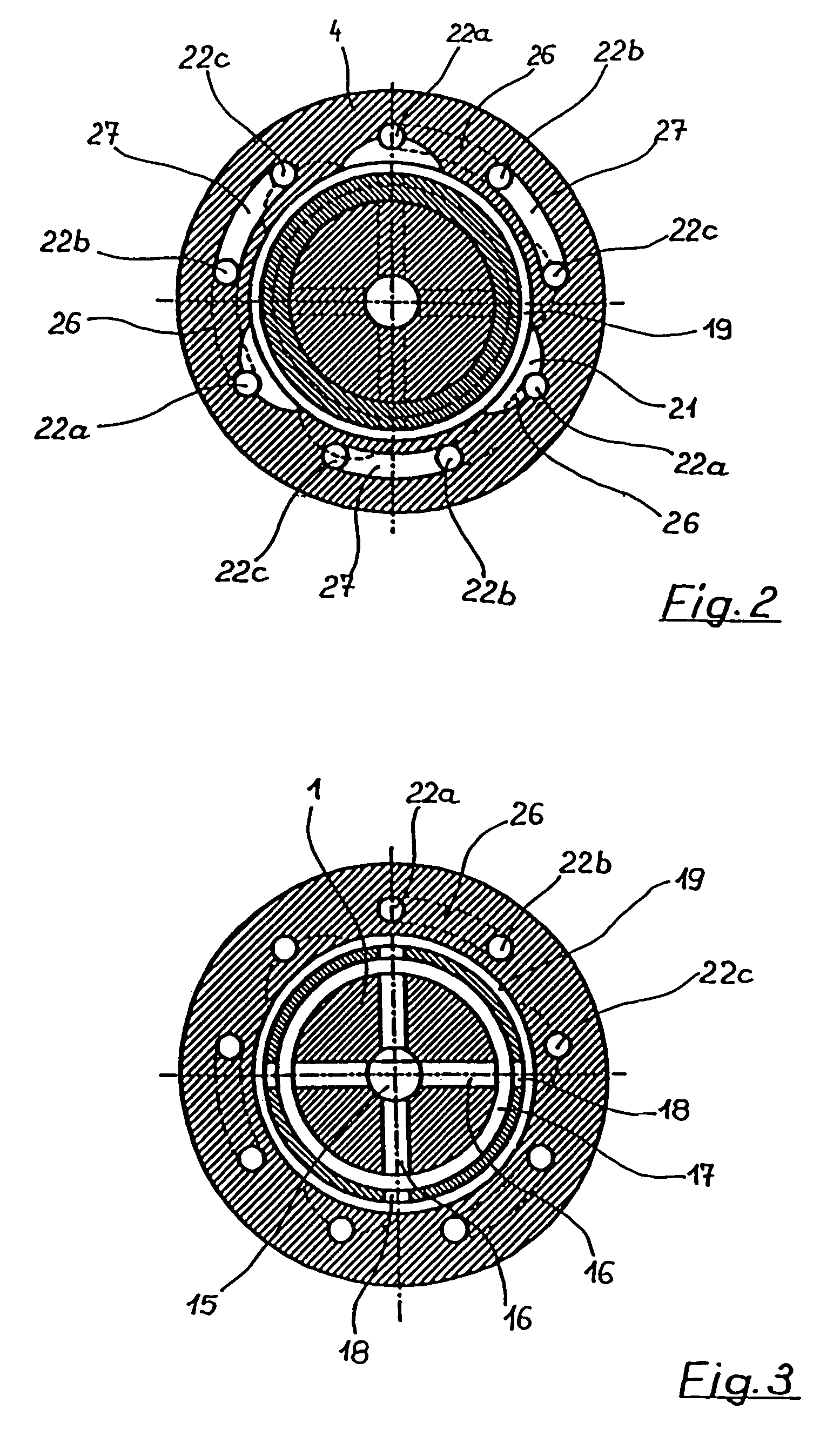
[0035]The illustrations in the figures show a strand-guiding roll according to the invention in diagrammatic form, this roll being suitable, for example, for use in a strand-guiding system of a continuous casting installation for producing metal strands of a considerable width with a slab or thin slab cross section. Identical or equivalent components in different embodiments are denoted by the same reference designations.

[0036]The strand-guiding roll illustrated in FIG. 1 comprises a continuous, central shaft 1, which is supported rotatably in four bearings 2. The bearings and the bearing housings 3 which carry them are for their part supported in a strand-guiding stand (not shown) of a continuous casting installation. The bearings used are usually rolling-contact bearings. The central shaft 1 is assigned three roll shells 4, each of the three roll shells being supported directly on the shaft 1. During the production phase of the continuous casting installation, the roll shell outer...


PUM

PropertyMeasurementUnit
distanceaaaaaaaaaa
distanceaaaaaaaaaa
temperatureaaaaaaaaaa

Abstract

An internally cooled strand-guiding roll for a continuous casting installation, having a central rotatable shaft and at least one roll shell supported fixed against rotation on the shaft. To make the strand-guiding roll better able to withstand the mechanical and thermal stresses, to ensure that it is suitable for large strand widths and to enable maintenance work to be carried out, the roll shell has coolant passages passing through it, and the coolant passages are arranged in the roll shell at a constant distance from the cylindrical roll shell outer surface of the roll shell and preferably at the area between the shaft and the roll shell. It is preferable for at least one water guide ring to be arranged between the roll shell and the central shaft.

Description

CROSS REFERENCE TO RELATED APPLICATIONS[0001]The present application is a 35 U.S.C. §§ 371 national phase conversion of PCT / EP2004 / 007399, filed Jul. 7, 2004, which claims priority of Austrian Application No. A 1132 / 2003, filed Jul. 18, 2003. The PCT International Application was published in the German language.BACKGROUND OF THE INVENTION[0002]The invention relates to an internally cooled strand-guiding roll, preferably for a continuous casting installation, having a central rotatable shaft and at least one roll shell which is supported fixed against rotation on this shaft.[0003]Strand-guiding rolls are used in continuous casting installations to support and guide continuously cast metal strands after they have emerged from a permanent mold in a strand-guiding stand. They are exposed to high thermal stresses, since the cast metal strands leave the mold at a temperature of over 1000° C., in particular in the case of steel strands. When producing relatively thick strands, especially ...

Claims


Application Information

Patent Timeline
Patent Type & Authority Patents(United States)
IPC IPC(8): B22D11/124B22D11/128F28F5/02
CPCF28F5/02B22D11/1287B22D11/124F16C13/02
Inventor DEIBL, GUNTHERGUTTENBRUNNER, JOSEFLANSCHUETZER, JOSEFPOEPPL, JOHANNSHAN, GUOXINTHOENE, HEINRICHWIMMER, FRANZ
Owner PRIMETALS TECH AUSTRIA GMBH
Why Eureka
Try Eureka