Method of depositing an anti-wear coating by thermal spraying

Inactive Publication Date: 2006-09-28
SN DETUDE & DE CONSTR DE MOTEURS DAVIATION S N E C M A +1
View PDF6 Cites 13 Cited by
  • Summary
  • Abstract
  • Description
  • Claims
  • Application Information

AI Technical Summary

Benefits of technology

[0009] An object of the invention is to propose a novel method of deposition that makes it possible to deposit anti-wear coatin

Problems solved by technology

These stresses in combination with vibratory movement damage and wear said surfaces.
The wear that is observed is found to be even greater when the blade roots and the fan or compressor disks are made of titanium or titanium alloy.
The microstructure of the coating deposited by plasma spraying nevertheless presents very high porosity and oxidation, thereby affecting the mechanical properties of the coating.
In addition, the coating adheres

Method used


Image

  • Method of depositing an anti-wear coating by thermal spraying
  • Method of depositing an anti-wear coating by thermal spraying

Examples


Example

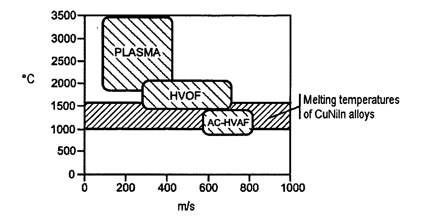
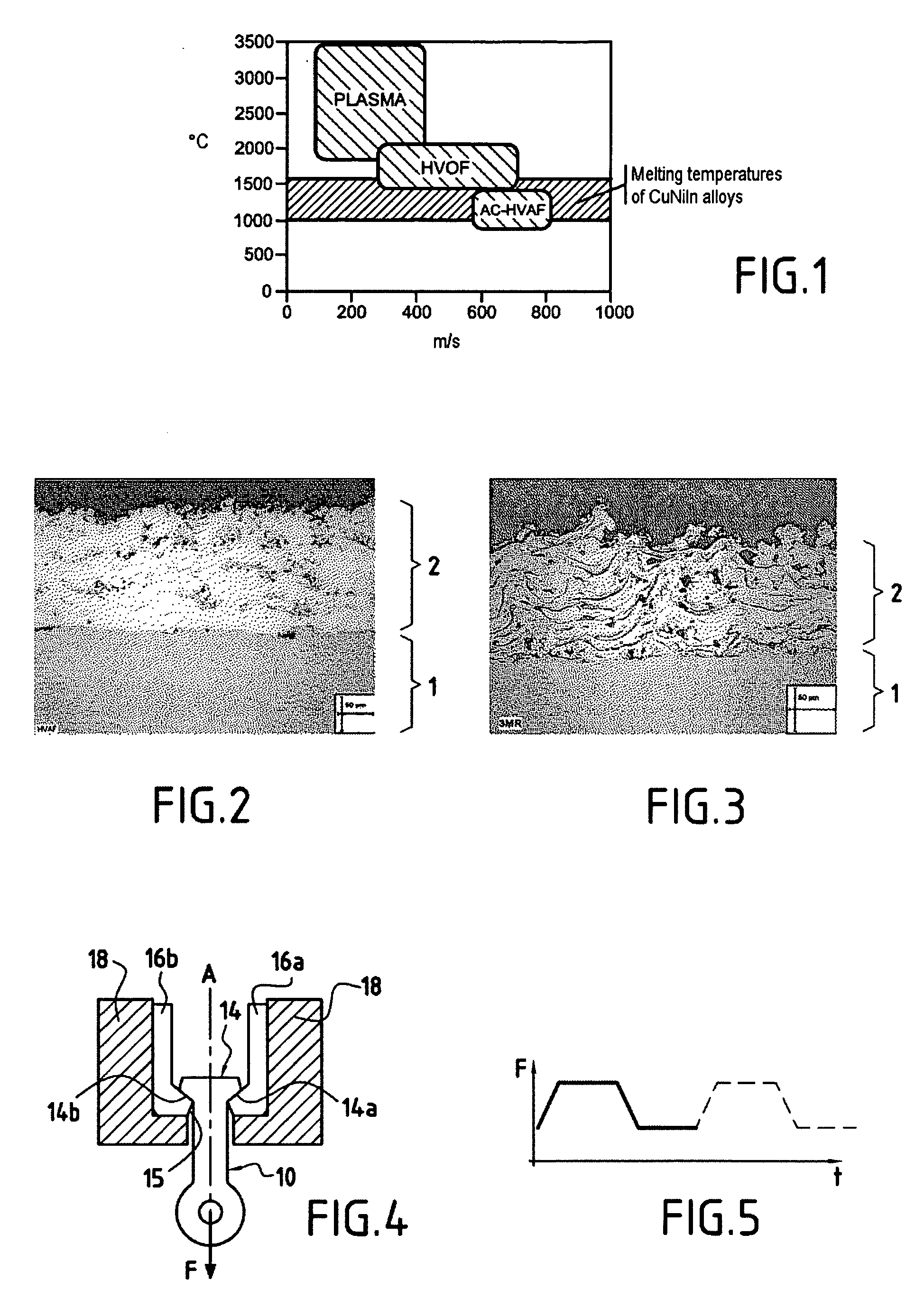
[0029] The plot of FIG. 1 has spray speed in m / s plotted along the abscissa and spray temperature in ° C. plotted up the ordinate, as obtained when using various thermal spraying methods. In this plot, there can be seen outlines for temperature and spray speed ranges for plasma, HVAF, and AC-HVAF spraying. Furthermore, the range of temperatures over which a copper-based alloy such as the CuNiIn alloy melts is also shown.

[0030] In this diagram, and as described above, it can be seen that the temperatures reached in AC-HVAF spraying are adapted to the melting range of the CuNiIn alloy used in the invention, thus making it possible to melt these alloys without useless overheating that would encourage oxidation. Furthermore, it can also be seen that higher spraying speeds can be obtained by using AC-HVAF spraying.

[0031] An implementation of the method of the invention is described below by way of example, in which a CuNiIn alloy was deposited on a part made of a titanium alloy of the ...


PUM

PropertyMeasurementUnit
Fractionaaaaaaaaaa
Fractionaaaaaaaaaa
Fractionaaaaaaaaaa

Abstract

A method of depositing an anti-wear coating on a mechanical part by thermal spraying of the AC-HVAF type, said coating being made of a copper-based alloy containing 30% to 42% by weight of nickel and 4% to 6% by weight of indium.

Description

[0001] The invention relates to a method of depositing an anti-wear coating on a mechanical part by thermal spraying, and more particularly it relates to a gas turbine part made of titanium or titanium alloy such as a fan blade or a compressor blade of a turbomachine. BACKGROUND OF THE INVENTION [0002] Fan or compressor blades constitute good examples of parts that are subjected to wear while a turbine is in operation. Such blades are held by their roots in slots of appropriate shape that are formed in the peripheries of rotary disks, referred to below as compressor disks or fan disks. [0003] While a turbojet is in operation, the blade roots move in said slots under the effects of centrifugal force and of vibration. The roots of blades are shaped in a manner that matches the shapes of the slots so as to make such relative displacements possible. The surfaces of blade roots that come to bear against the edges of said slots under the effect of centrifugal force are subjected to signif...

Claims


Application Information

Patent Timeline
IPC IPC(8): C23C4/00
CPCC23C4/06C23C4/12F01D5/288F05D2230/31F05D2300/1723
Inventor BENGTSSON, PERDUDON, LAURENT PAULGUELDRY, GERARD MICHEL ROLANDHACALA, MICHEL
Owner SN DETUDE & DE CONSTR DE MOTEURS DAVIATION S N E C M A
Why Eureka
Try Eureka