
Methods and system for crossing prediction

a technology for crossings and prediction circuits, applied in the direction of traffic crossing safety means, railway signalling, transportation and packaging, etc., can solve the problems of pedestrians in particular beginning to move across the gates, difficult to obtain accurate warning times, and difficult for the prediction circuit to tell the difference between noise and motion on the track

Active Publication Date: 2013-10-17
GENERAL ELECTRIC CO
View PDF19 Cites 12 Cited by
  • Summary
  • Abstract
  • Description
  • Claims
  • Application Information

AI Technical Summary

Benefits of technology

The patent describes a method for sensing and tracking a vehicle's position and velocity using data from a vehicle's sensor. The method filters the sensor data to improve accuracy and consistency, and then uses the filtered data to determine the time it takes for the vehicle to cross an intersection or other obstacle. The technical effects of this invention include improved accuracy and consistency in vehicle position and velocity sensing, which can lead to safer and more efficient driving habits.

Problems solved by technology

However, when the position signal deteriorates or is subject to a large amount of noise, it can be very difficult to obtain accurate warning times. Thus, if the position signal is too noisy, it is difficult for the prediction circuit to tell the difference between noise and motion on the track.
Long warning times often are the result of noisy signals that make the train appear closer than it actually is.
If a warning time is too long, pedestrians in particular may begin to move across the gates, assuming that the warning is a false alarm.

Method used


Image

  • Methods and system for crossing prediction
  • Methods and system for crossing prediction
  • Methods and system for crossing prediction

Examples


Embodiment Construction

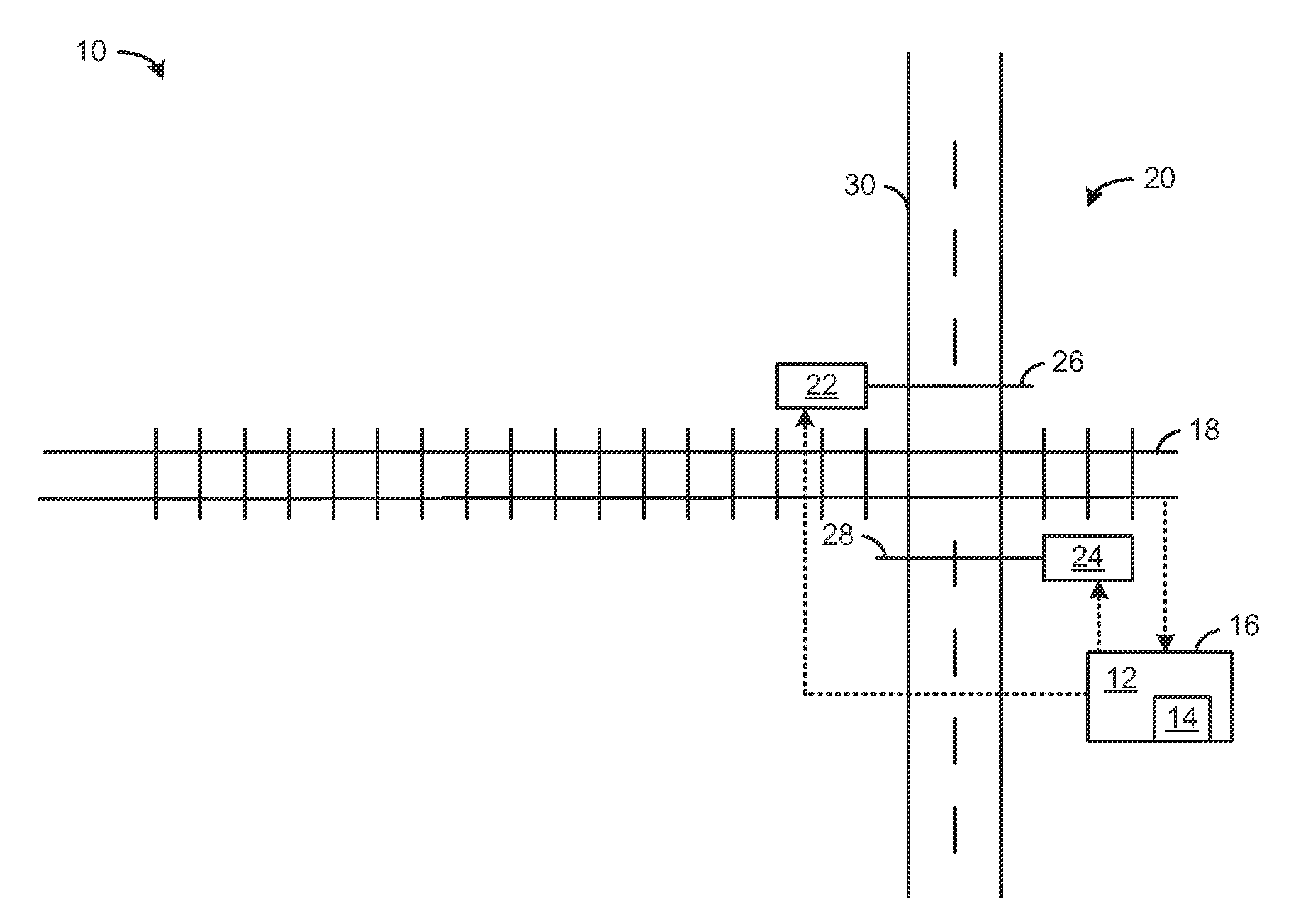
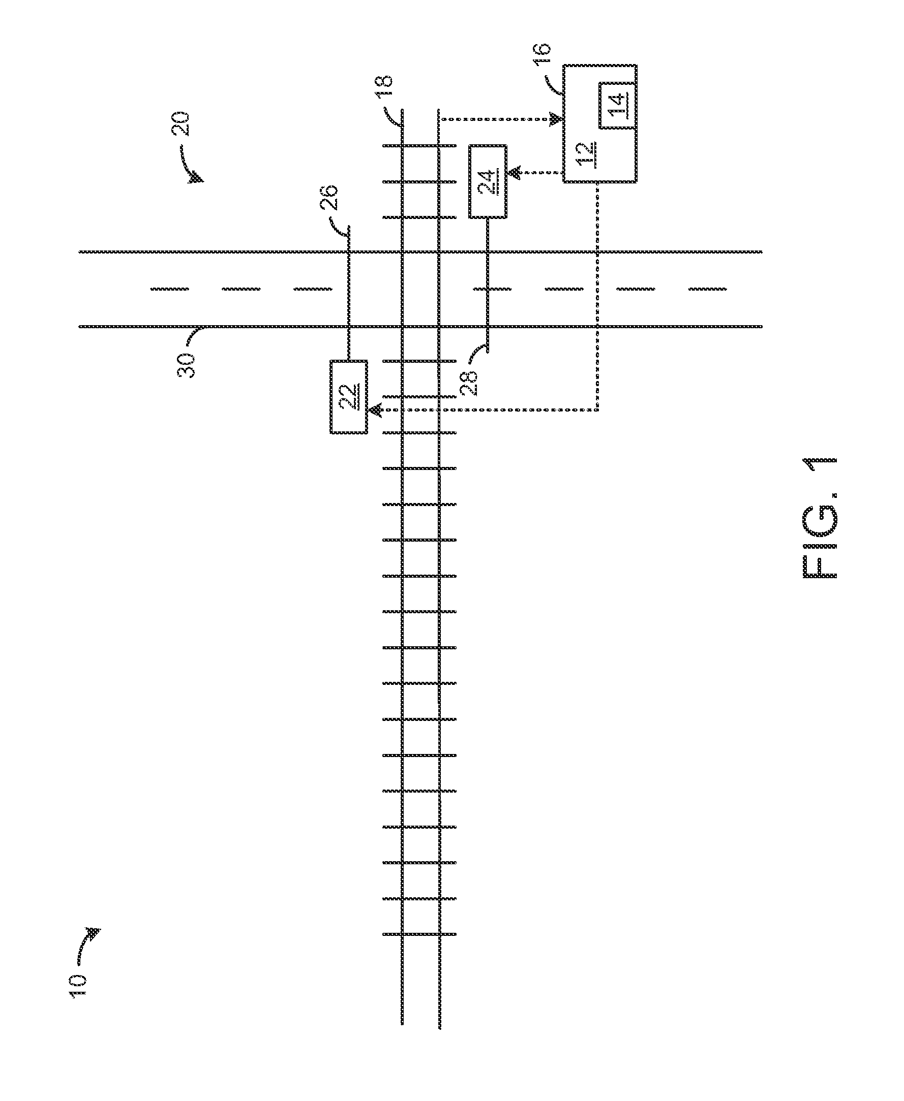
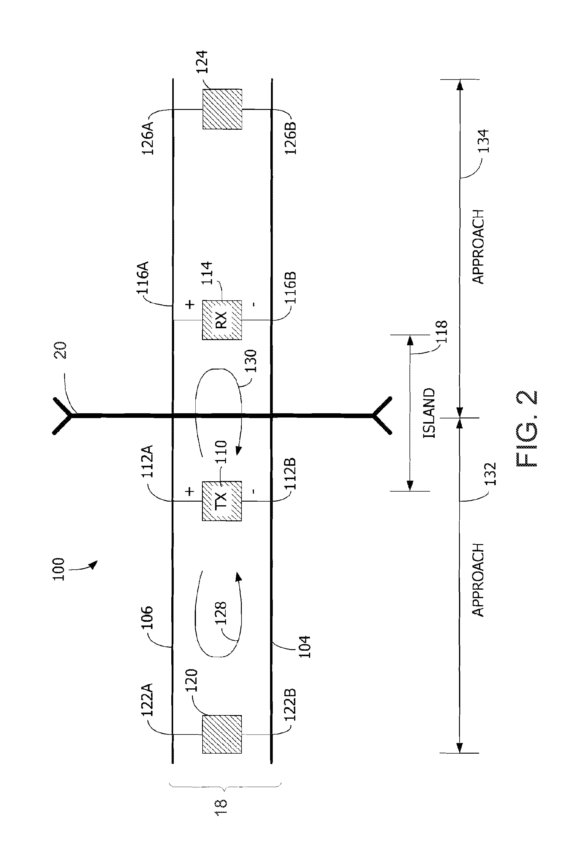
[0012]The following description relates to various embodiments of a crossing prediction system. In particular, in an embodiment of the system, a controller associated with a crossing includes an algorithm that improves warning time accuracy when the position signal is distorted. The system guards against both short and long warning times and reduces the risk of both long and short warning times resulting from distorted prediction signals. In one example, the system (e.g., as carried out by the controller executing the algorithm) may utilize a smoothened velocity signal. As velocity of a vehicle, such as a train, is likely to change relatively slowly, the crossing predication time may be based on averaged velocity rather than averaged position. In this way, warning time accuracy may be increased.

[0013]FIG. 1 is a simplified block diagram of a crossing system 10 according to one embodiment of the invention. Crossing system 10 includes a crossing 20 where a first vehicle path intersect...


PUM


Abstract

Various methods and systems are provided for predicting crossing times. In one embodiment, a method comprises determining a vehicle position of a vehicle from sensed data, filtering the vehicle position, determining vehicle velocity based on the filtered vehicle position, filtering the vehicle velocity to a greater extent than vehicle position is filtered, at least above a threshold frequency, and determining a time-to-crossing based on the filtered vehicle position and filtered velocity.

Description

FIELD[0001]Embodiments of the subject matter disclosed herein relate to a vehicle crossing prediction system.BACKGROUND[0002]Railroad crossing prediction circuits deliver warning times prior to a train or other vehicle reaching a crossing, based on a position signal, for example. However, when the position signal deteriorates or is subject to a large amount of noise, it can be very difficult to obtain accurate warning times. Thus, if the position signal is too noisy, it is difficult for the prediction circuit to tell the difference between noise and motion on the track. Short warning times usually occur when motion is detected too late for the predictor to give adequate warning time. Long warning times often are the result of noisy signals that make the train appear closer than it actually is. Short warning times can prevent pedestrians, automobiles, and other transportation vehicles from having enough notice to stop prior to a train reaching the crossing. If a warning time is too l...

Claims


Application Information

Patent Timeline
Patent Type & Authority Applications(United States)
IPC IPC(8): B61L29/18
CPCB61L29/226
Inventor STEFFEN, II, MICHAEL W.ISAACSON, BRIAN WESLEY
Owner GENERAL ELECTRIC CO
Learn More