Door lever assembly

Active Publication Date: 2013-10-17
SECURITECH GROUP
View PDF16 Cites 7 Cited by
  • Summary
  • Abstract
  • Description
  • Claims
  • Application Information

AI Technical Summary

Benefits of technology

The invention is a new door lever with no gaps or access points between the lever and the door surface, making it difficult for a ligature (a thin rope or wire) to be inserted. The lever has a flat plate on the bottom that pivots with the stem, eliminating the gap. The lever is made of a strong and durable metal or plastic material. The lever also has elongated recesses on its surface for easy gripping. These features improve the functionality and safety of the door lever.

Problems solved by technology

However, there remain some situations where the ligature can become wedged in the area of the pivot or shaft connection at the base of the handle, namely wedged between the bottom surface of the handle and the surface of the door.

Method used


Image

  • Door lever assembly
  • Door lever assembly
  • Door lever assembly

Examples


Embodiment Construction

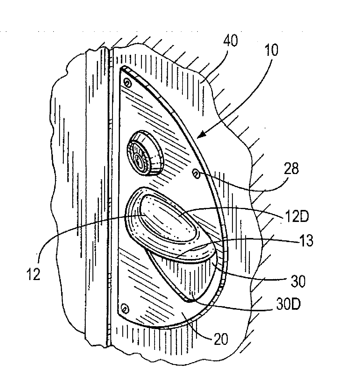
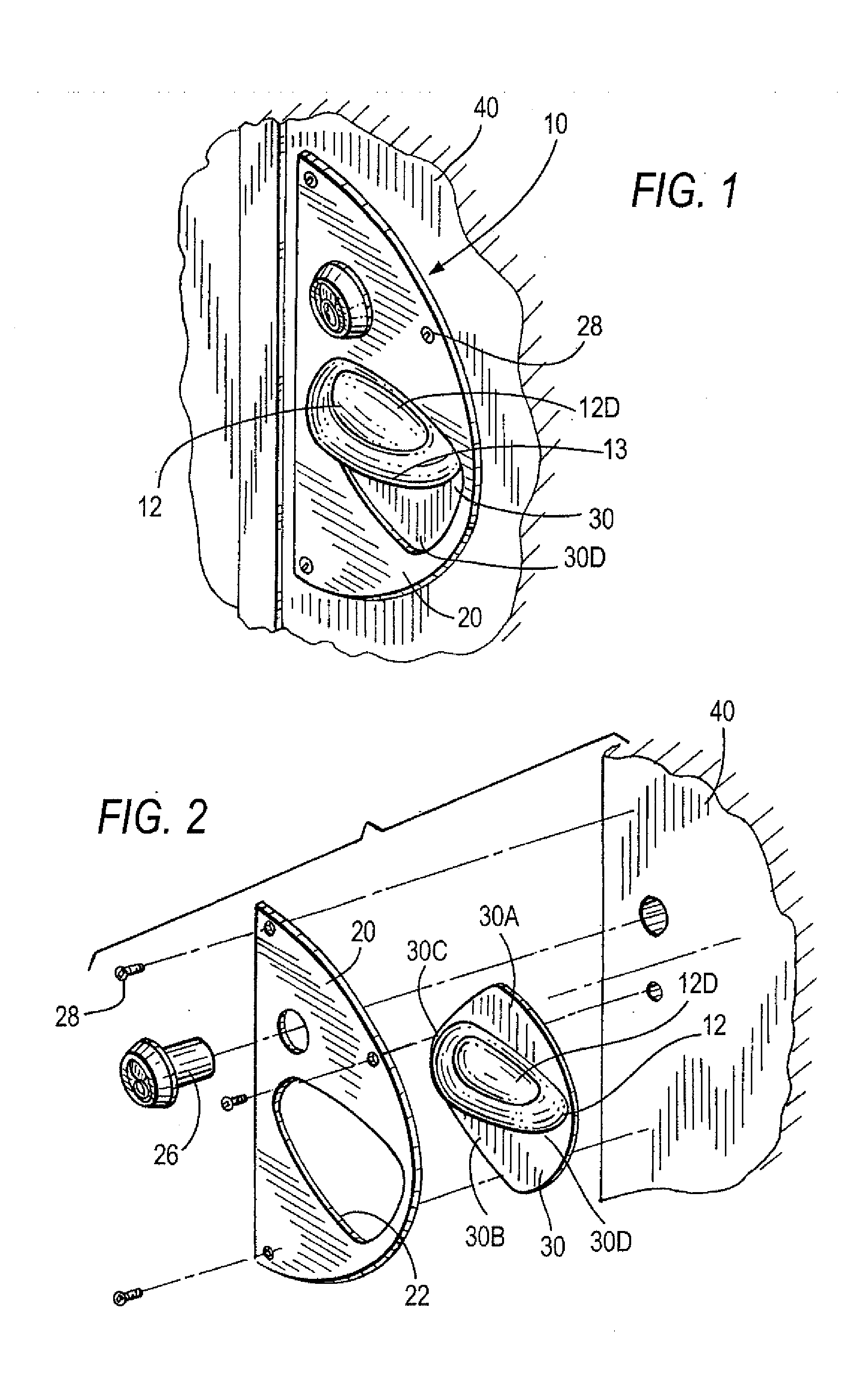
[0040]The new door lever assembly 10 is shown in FIG. 1 as installed on door 40, and is shown in exploded view in FIG. 2. This door lever assembly comprises the basic components, lever 12, pivot plate 30 and face plate 20 mountable on the face of the door.

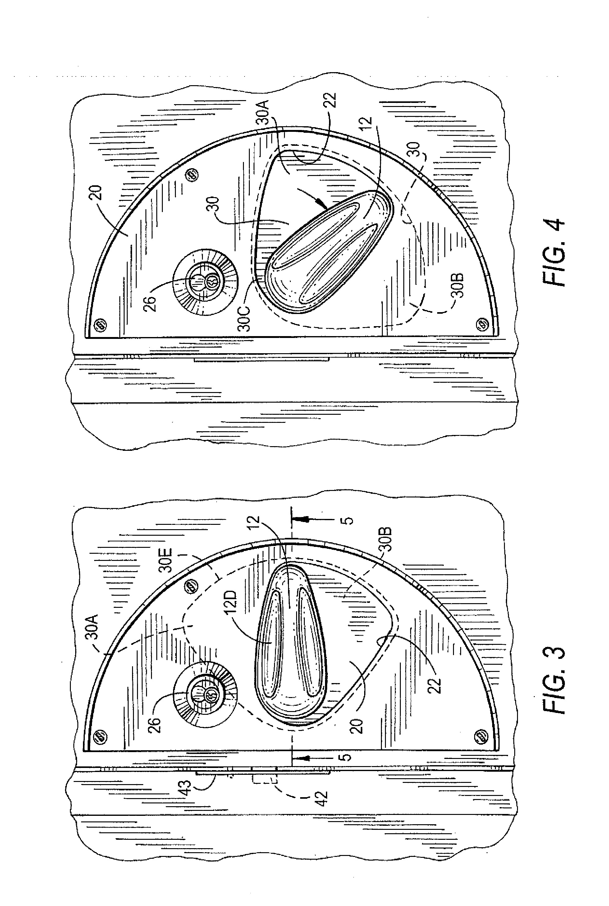
[0041]As best seen in FIGS. 1 and 5, lever 12, also called “mouse lever” because if its shape being generally similar to a computer mouse, has an elongated smooth humped top surface 13, a front end 14, tail end 16 and a flat bottom surface 17. Lever 12 is secured to pivot axle 18 by any conventional connection means 19 which may be pinned, splined, friction or interference fit, with the axle 18 coupled via a conventional door lock latch mechanism not shown to latch bolt 42 which can engage strike plate 43 seen in FIG. 3. The lever's mouse shape is smooth on front, tail and side surfaces, such that any ligature in contact with or wrapped about this lever, will quickly slide off, as there is no area about which a ligature can loop ab...


PUM


Abstract

A lever and mounting plate combination attachable to the exposed vertical surface of a door that includes a latch assembly with a spindle extending horizontally outward from the vertical surface, the lever and mounting plate combination including a main plate mountable onto the door's exposed surface and having a window-like opening extending completely through the plate, a lever having a base part which is coupleable to the spindle and pivotable therewith and has an exposed outer part, and a lever plate fixed to the base part of the lever and pivotable with though lever and with the spindle when it is coupled to the lever, the lever plate closely underlies and contacts said inner surface of the main plate while at all times covering the window, the lever being engagable by a user to rotate the the lever plate and simultaneously rotate the spindle to open the door.

Description

BACKGROUND[0001]1. Field of the Invention[0002]This invention is in the field of door levers for security doors and particularly for door levers for doors of residential rooms in mental institutions where patients reside.[0003]2. Prior Art[0004]This invention relates to a serious problem where certain patients in behavioral health care facilities or psychiatric institutions try to commit suicide by hanging themselves with a cord or other ligature form looped over the top of a door and secured to a handle or knob of the door to the patient's room. This invention relates to methods and apparatus seeking to prevent such attempted suicides. Reasons for such behavior are complex and not the subject of the present invention; however, significant numbers of attempts do occur, and significant numbers of patients are committed into these institutions for the very reason that they are known to be candidates for suicide attempts. These institutions are supposed to be environments for treatment...

Claims


Application Information

Patent Timeline
IPC IPC(8): E05B1/00
CPCE05B1/003E05B15/02Y10T292/57
Inventor BERGER, MARK J.REGEN, JEFFREY
Owner SECURITECH GROUP
Why Eureka
Try Eureka