Ring cam and fluid-working machine including ring cam

a fluid-working machine and ring cam technology, applied in cams, climate sustainability, energy industry, etc., can solve the problems of large ring cam machines that are difficult and expensive to repair, large fluid-working machines (such as those suitable for renewable energy generation) are typically subject to particularly high internal forces and pressures, and achieve the effect of reducing the gap

Inactive Publication Date: 2012-10-18
ARTEMIS INTELLIGENT POWER
View PDF2 Cites 4 Cited by
  • Summary
  • Abstract
  • Description
  • Claims
  • Application Information

AI Technical Summary

Benefits of technology

[0123]The cam segment support may extend continuously between at least two said fixtures and typically between each said fixture, and preferably the step of mounting a ring cam segment comprises bringing the support facing surface of the segment into engagement with the cam segment support at or near to the leading and trailing ends of the segment, such that there is a gap between the support facing surface and the support extending at least part way between the leading and trailing ends of the segment (typically across the centre of the segment) and elastically deforming the segment to reduce (and preferably, eliminate) the gap. The segment may be elastically deformed when bolts connecting the segment to the cam segment support are tensioned.

Problems solved by technology

Large ring cam machines are difficult and expensive to repair, requiring disassembly of the whole body to repair even one working chamber.
This may be particularly expensive in renewable energy applications because a heavy fluid-working machine must be moved from an inaccessible location (for example the nacelle of a wind turbine) requiring concomitantly large and costly transportation equipment (e.g. a crane).
Furthermore, large fluid-working machines (such as those suitable for renewable energy generation) are typically subject to particularly high internal forces and pressures.
Consequently the forces received by the ring cam from the rollers are also high, and it is known for the ring cam working surfaces to degrade.
It has been proposed to assemble large scale ring cams from a number of segments, and it is known for excessive wear to occur to the roller and to the working surface due to discontinuities which appear on the working surface under pressure of a roller at the interface between segments.
Additionally, the weight of the rotating parts themselves may lead to excessive ring cam wear.

Method used


Image

  • Ring cam and fluid-working machine including ring cam
  • Ring cam and fluid-working machine including ring cam
  • Ring cam and fluid-working machine including ring cam

Examples


Embodiment Construction

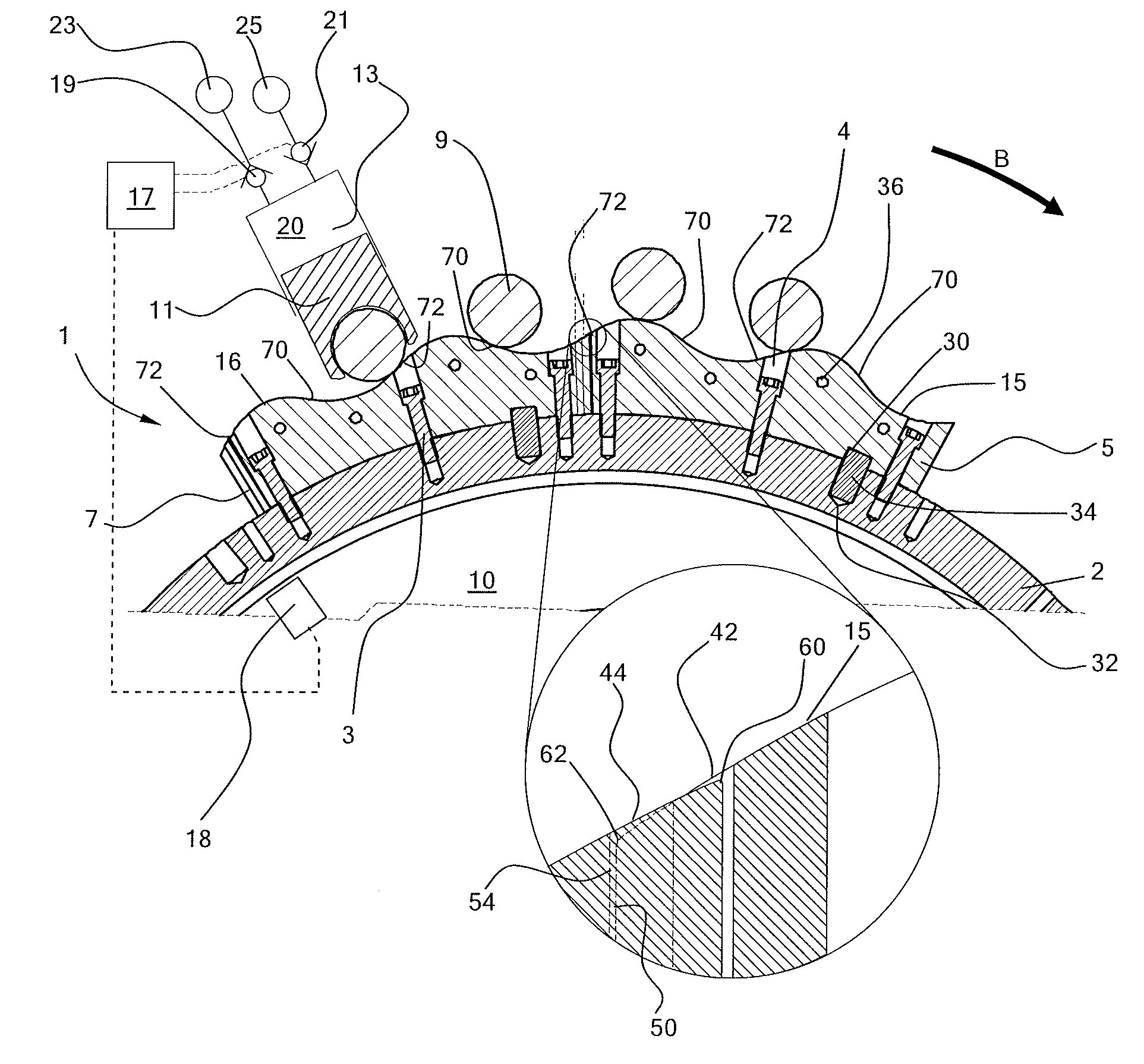
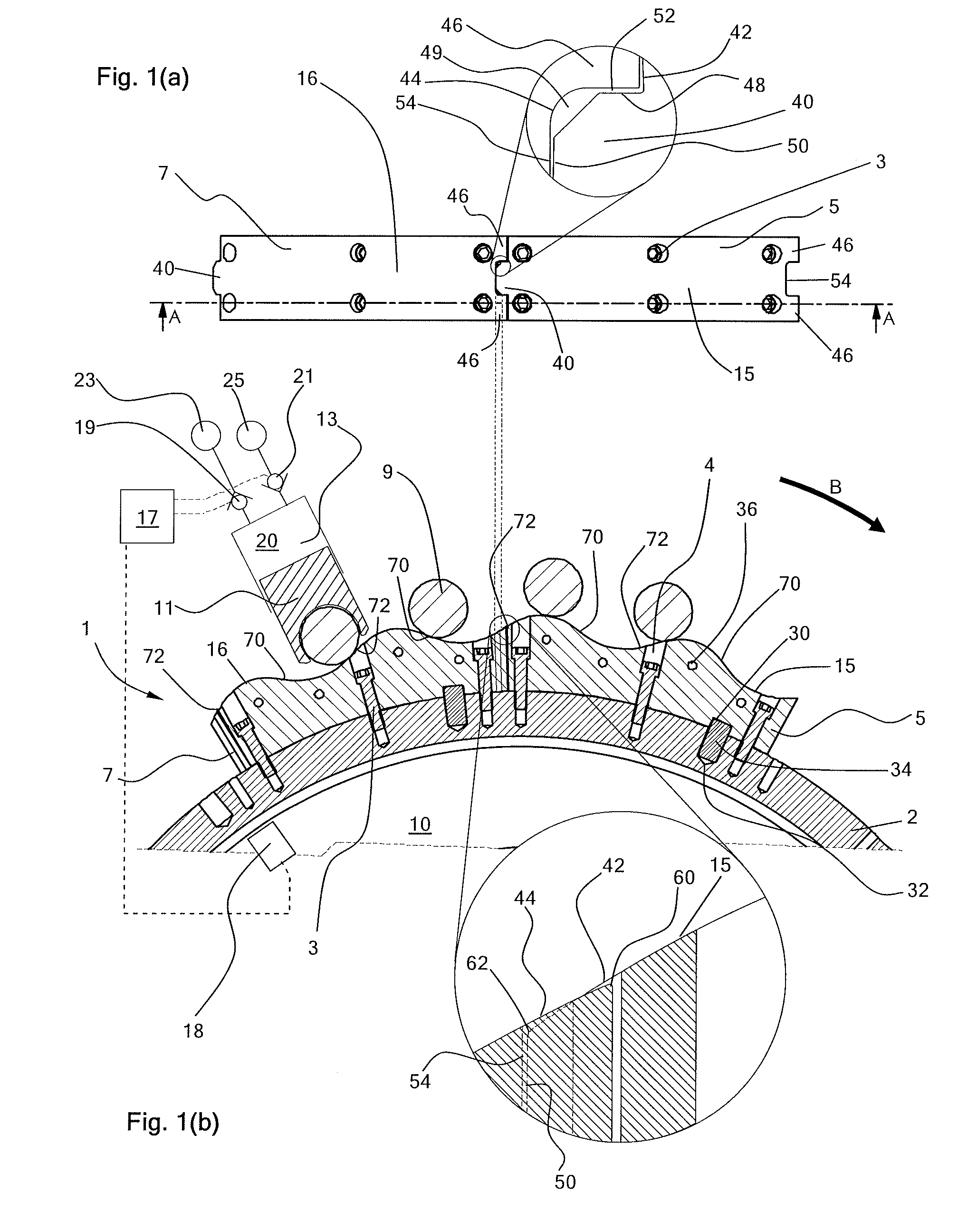
[0136]With reference to FIG. 1(b), a portion of a ring cam 1 is formed from cam segments 5 and 7, secured by bolts 3 which extend from apertures 4 in the surface of the cam segments and fix the cam segments to a cam support structure 2. A plurality of further cam segments (not shown) are securable to the cam support structure, to make up the complete ring cam. The cam support structure is coupled to drive shaft 10 (which rotates in direction B in normal use) through which torque is received from an energy source (e.g. the blades of a wind or tidal turbine).

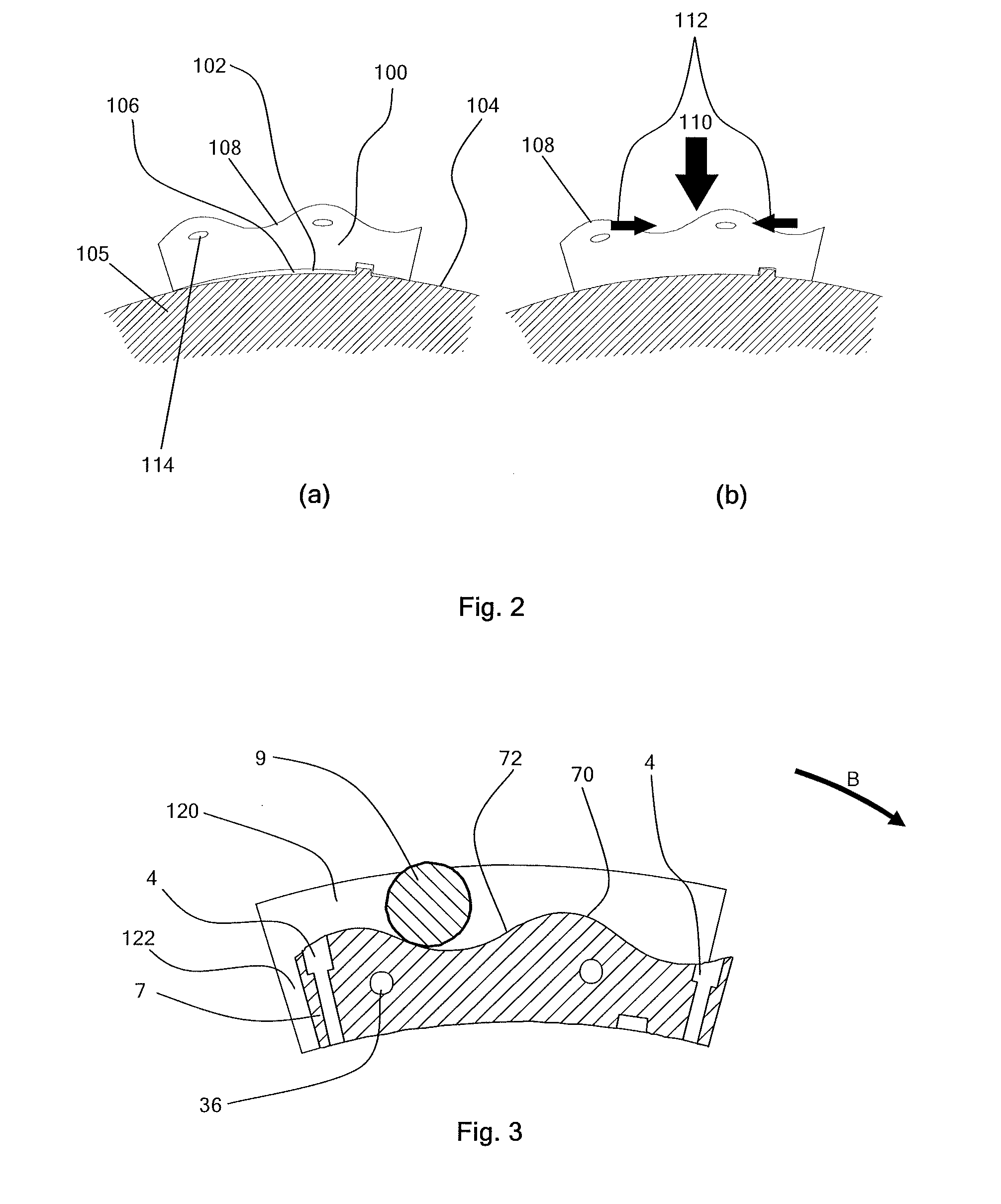
[0137]Each cam segment has a piston facing surface 15, 16 which defines a portion of the working surface of the ring cam. Thus, the ring cam has a working surface defined by a plurality of cam segments secured around the circumference of the drive shaft. The working surface is wave-like and comprises a plurality of waves having leading surfaces 70 and trailing surfaces 72 (defined relative to the direction of rotation). The waves ...


PUM


Abstract

A fluid-working machine comprising a ring cam, at least one piston defining a working chamber, and at least one valve associated with the or each working chamber for connecting the working chamber alternately to low and high pressure manifolds in phased relationship to cycles of working chamber volume. The ring cam has a wave-like cam working surface for operative engagement with the at least one piston. The waves of the wave-like cam surface each having a leading face and a trailing face and discontinuities, such as apertures to retain bolts, are located in the working surface on whichever of the leading face and the trailing face the at least one piston does least work during normal operation resulting from the flow of fluid into and out of the working chamber in phased relationship to cycles of working chamber volume.

Description

FIELD OF THE INVENTION[0001]The invention relates to a ring cam for a fluid-working machine. The invention is of especial relevance in applications where ring cams are subjected to particularly large forces in use, and in particular to ring cams for large fluid-working machines, for example for use in the nacelle of a wind turbine.BACKGROUND TO THE INVENTION[0002]Fluid-working machines include fluid-driven and / or fluid-driving machines, such as pumps, motors, and machines which can function as either a pump or as a motor in different operating modes.[0003]When a fluid-working machine operates as a pump, a low pressure manifold typically acts as a net source of a working fluid and a high pressure manifold typically acts as a net sink for a working fluid. When a fluid-working machine operates as a motor, a high pressure manifold typically acts as a net source of a working fluid and a low pressure manifold typically acts as a net sink for a working fluid. Within this description and th...

Claims


Application Information

Patent Timeline
Patent Type & Authority Applications(United States)
IPC IPC(8): F01L15/00
CPCF04B9/042F03C1/053F16H53/025F01B1/0648F04C23/02F04B27/0414F03C1/0409F03C1/04F01B1/062F04B49/065F04B17/02F04B1/0413F04B1/053F04B1/04F03C1/0466F04B1/066Y02P80/10F01B9/06F04B1/06F04B9/04
Inventor RAMPEN, WILLIAM HUGH SALVINFOX, ROBERT GEORGE
Owner ARTEMIS INTELLIGENT POWER
Why Eureka
Try Eureka