Printer and platen roller for printer

Inactive Publication Date: 2013-10-17
SATO HLDG CORP
View PDF2 Cites 0 Cited by
  • Summary
  • Abstract
  • Description
  • Claims
  • Application Information

AI Technical Summary

Benefits of technology

The present invention provides a printer and printer platen roller that can print on a print paper with a gap between sheets. This is possible without using expensive and complicated equipment such as a controller. The printer platen roller is simple to operate and can handle different gap dimensions. This results in high-quality printing and ensures consistent printing quality.

Problems solved by technology

This generates problems because the adhesive may attach to the neighboring adhesives or to another sheet, or the adhesive may protrude from the outer edge of the label.
However, when printing is made on the double-sided label continuum having the above described gap 58, this generates a problem that printing precision decreases, because appropriate pressure necessary for printing is not applied to a portion of the coloring layer which is pressed to the platen roller 59 through the gap 58 and performs printing, the heat generation of the thermal head 60 is not transmitted to the coloring layer, and so printing is not made in the part.

Method used


Image

  • Printer and platen roller for printer
  • Printer and platen roller for printer
  • Printer and platen roller for printer

Examples


example 1

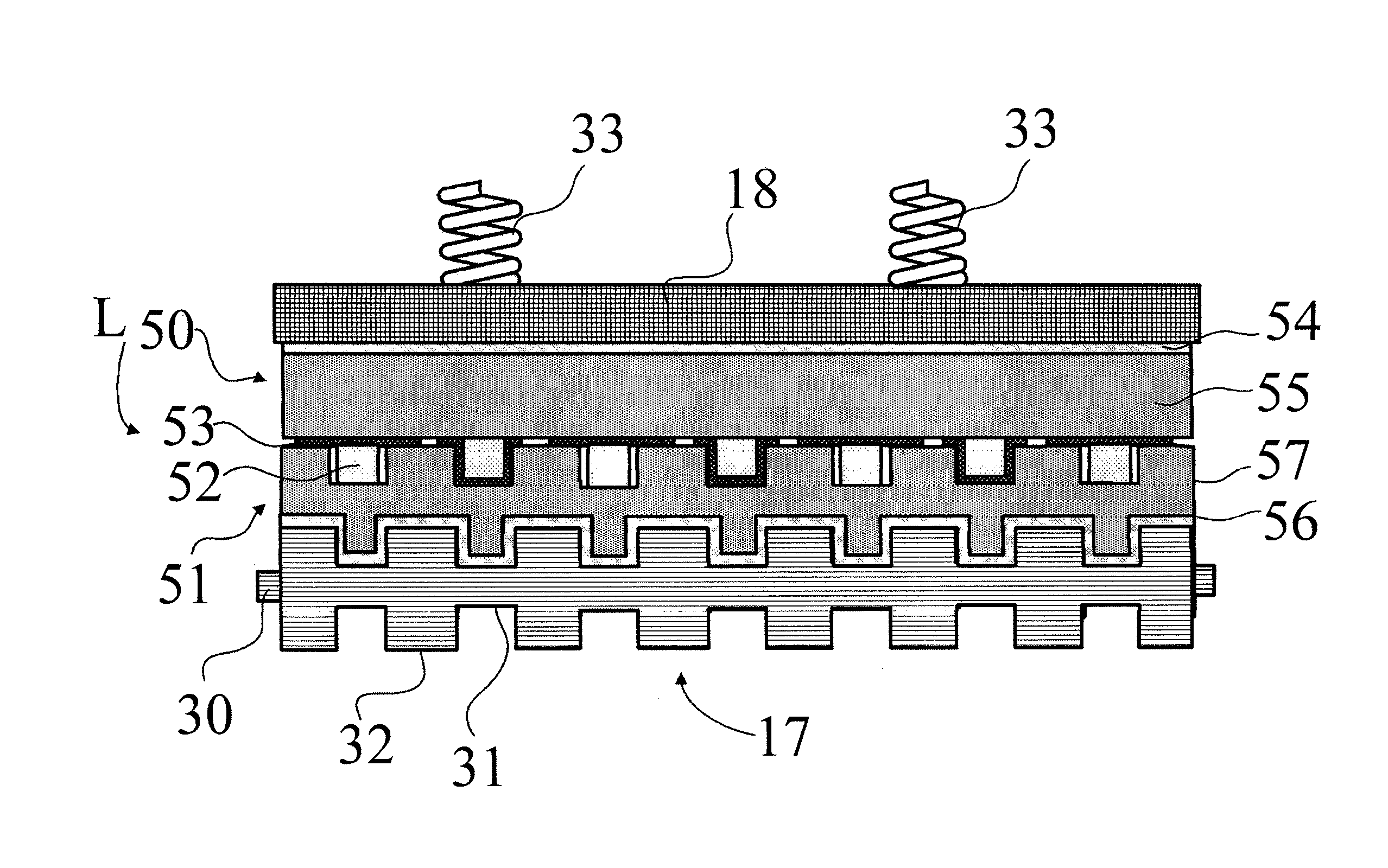
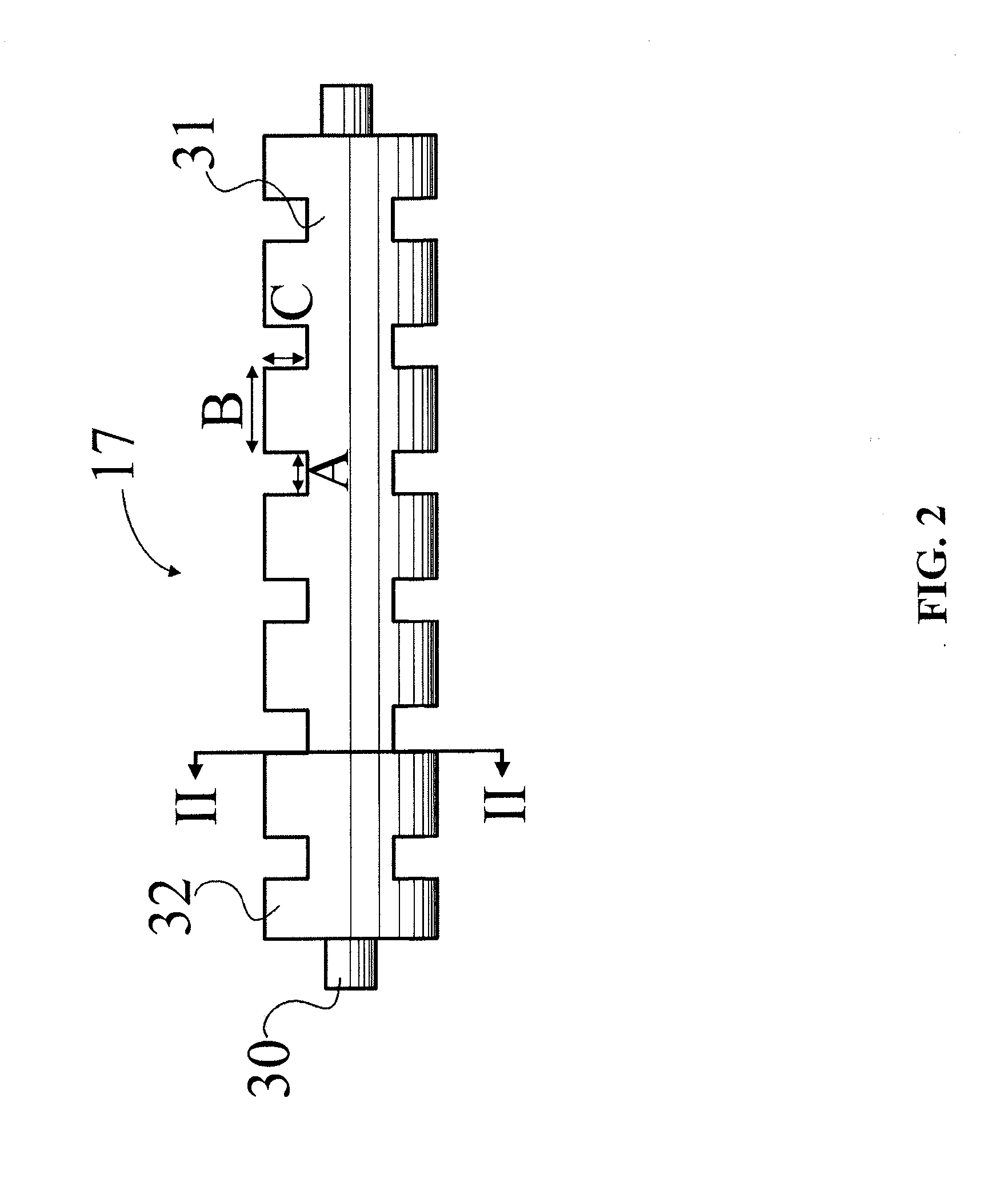
[0018]The example 1 shall be described with reference to FIGS. 1 to 4. In addition, in the following, for the same parts as those in the conventional art, only the same signs are assigned and duplicated descriptions are omitted.

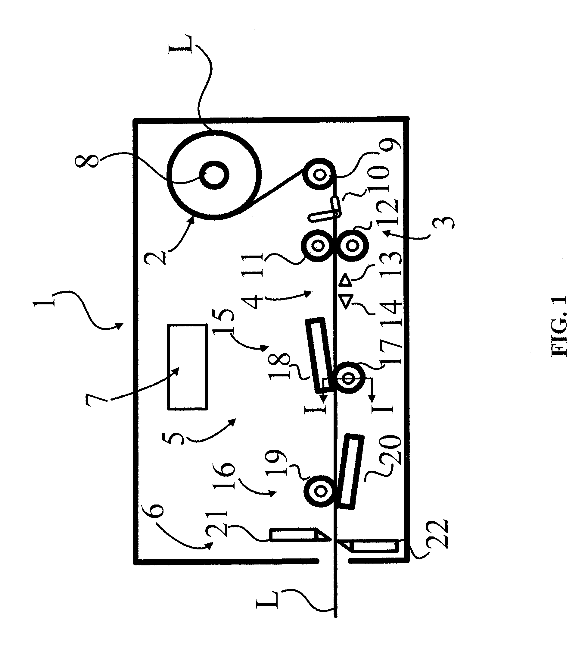
[0019]FIG. 1 is a side view of a double-sided label printer 1 according to the example 1 of the present invention. As shown in the Figure, the double-sided label printer 1 is comprised of a label supply section 2, a label feed section 3, a label detection section 4, a label print section 5, a label cut section 6, and a control section 7.

[0020]The label supply section 2 is configured so as to mount a rolled double-sided label continuum L to a label supply reel 8, and to supply the double-sided label continuum L to the label feed section 3.

[0021]The label feed section 3 is comprised of a guide roller 9, a label width regulating guide 10, a driven roller 11, and a drive roller 12. The guide roller 9 is disposed rotatably at an upstream position from the label pr...

example 2

[0034]Next, the first platen roller 40 according to the example 2 shall be described with reference to FIGS. 5 and 6. Description of the second platen roller (not shown) having the same configuration as that of the first platen roller 40 shall be omitted. With regard to the similar portions as those in the example 1, only the same reference sign shall be assigned, and duplicated description shall be omitted.

[0035]FIG. 5 is a front view of the first platen roller 40 according to the example 2. As shown, the first platen roller 40 is comprised of a shaft 41, a roller body 42 and projections 43. The shaft 41 has the same configuration as that of the shaft 30, and so description is omitted.

[0036]The roller body 42 has an empty central axis and is made of an elastic body such as an urethane rubber, a silicone rubber, etc. The shaft 41 is inserted into the empty central axis at a predetermined interval and is fixed. When the shaft 41 is rotationally driven, the roller body 42 is also rota...


PUM


Abstract

A printer 1 comprising, a feed section 3 capable of feeding a print paper having a first sheet 50 and a second sheet 51 laminated to the first sheet 50 through a gap 58, and a print section 5 for printing the print paper, wherein the print section 5 comprises a thermal head 18 and a platen roller 17 being opposed to the thermal head 18, wherein the platen roller 17 comprises a shaft 30 being rotatably supported in a direction perpendicular to a feeding direction of the print paper, a cylindrical body roller 31 disposed to the shaft 30, and a projecting portion 32 protruding outward in a radial direction of the body roller 31 for filling the gap 58 by pressing the print paper.

Description

CROSS-REFERENCE TO RELATED APPLICATIONS[0001]The present application is a 35 U.S.C. §§371 national phase conversion of PCT / JP2011 / 007126, filed Dec. 20, 2011, which claims priority of Japanese Patent Application No. 2010-284051, filed Dec. 21, 2010 and Japanese Patent Application No. 2011-021316, filed Feb. 3, 2011, the contents of which are incorporated by reference herein. The PCT International Application was published in the Japanese language.[0002]The present invention relates to a printer a printer and a platen roller, and more particularly to a printer and a platen roller for applying appropriate printing pressure to a print paper.BACKGROUND ART[0003]Conventionally, a double-sided label strip or continuum with no backing sheet is known. It is made by laminating a first sheet and a second sheet. On each back side or inward facing surface of the first sheet and the second sheet, an adhesive and a remover are formed alternately at positions where the adhesive of one sheet attach...

Claims


Application Information

Patent Timeline
IPC IPC(8): B41J13/02
CPCB41J13/025B41J2/32B41J11/057B41J3/60B41J11/04
Inventor OTSUKA, MASANORIMOGI, MARIKO
Owner SATO HLDG CORP
Why Eureka
Try Eureka