Hybrid virtual load monitoring system and method

a monitoring system and virtual load technology, applied in the direction of testing/monitoring control systems, instruments, force/torque/work measurement apparatus, etc., can solve the problems of significant system variations, system configuration changes, damaged/worn parts, etc., and achieve the effect of improving the virtual sensor approach

Active Publication Date: 2013-10-17
SIKORSKY AIRCRAFT CORP
View PDF3 Cites 28 Cited by
  • Summary
  • Abstract
  • Description
  • Claims
  • Application Information

AI Technical Summary

Benefits of technology

[0010]A hybrid virtual load monitoring system and method according to the present invention improves the virtual sensor approach by including one or more direct or physical sensor measurements in addition to one or more virtual sensors comprising a hybrid virtual sensor network. The inputs to the hybrid virtual sensor network include the measured system state parameters. Additionally, physical sensor features are included as an input (as opposed to an output) in the mapping between system state parameters and the various target virtual sensor feature amplitudes.
[0012]In another possible implementation, the physical sensor measurement can be pre-processed to explicitly compute the feature amplitudes for that physical sensor location (based upon the measured time history and the previously stored feature structure). In this implementation, the physical sensor signals are in essence thus converted to a set of derived system state parameters. The addition of the physical sensor measurement, which is more strongly correlated to the measurements from the virtual target sensors, as an input increases the accuracy of predictions of measurements of the virtual sensor target locations.

Problems solved by technology

The error metric will indicate if model assumptions have been violated, meaning that the system state at the time of the measurement is outside the range of validity of the virtual sensor model (i.e., outside of the span of operating conditions used for training) or that some other significant system variations such as damaged / worn parts or system configuration changes have occurred.

Method used


Image

  • Hybrid virtual load monitoring system and method
  • Hybrid virtual load monitoring system and method
  • Hybrid virtual load monitoring system and method

Examples


Embodiment Construction

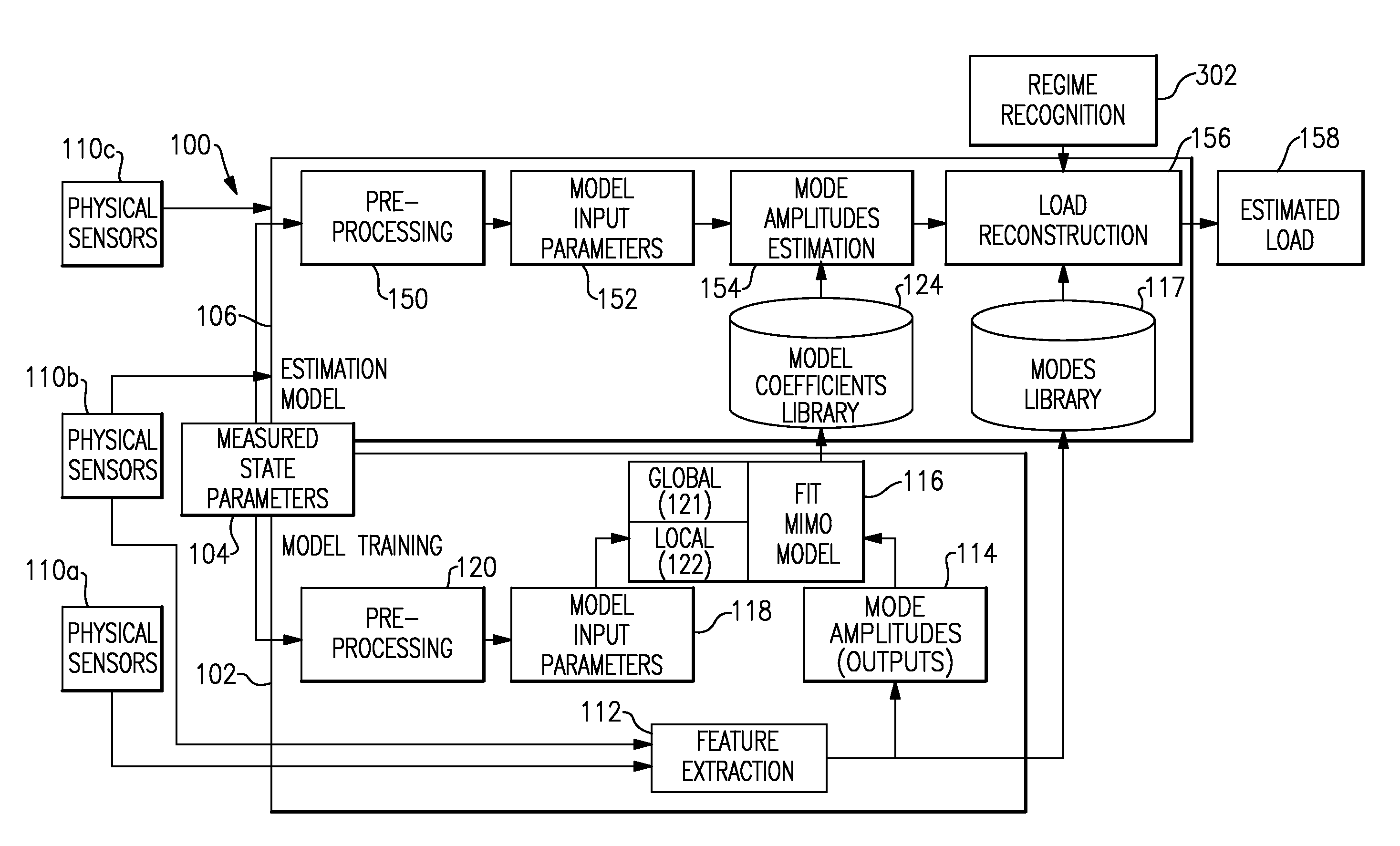
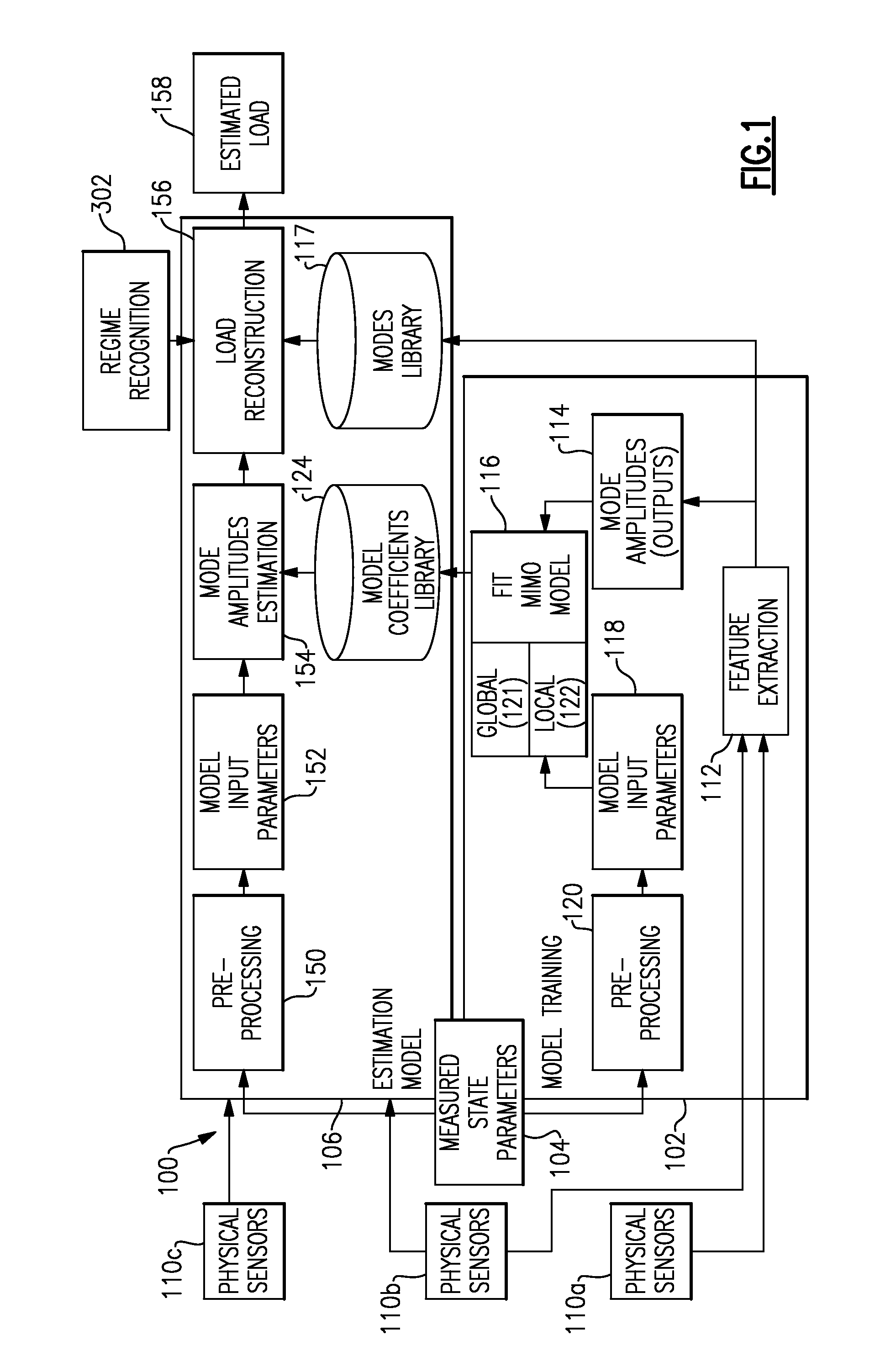
[0023]FIG. 1 illustrates one embodiment of an overall signal estimation system100 according to one embodiment of the invention. Although the description below focuses on load estimations, it is to be understood that the system and process can be used in any application where accurate signal estimates are desired.

[0024]1. Overview of Signal Estimation Concept

[0025]Data corresponding to loads applied on a part or a part's response to a load (collectively referred to as “loads” in this application) provides valuable information on how a component is being used. Generally, the system provides an implementation of a mathematical construct that acts as a virtual sensor to infer a measurement of a desired signal, such as a load, from easily available state parameters or other measured loads (e.g., pilot controls, aircraft weight, aircraft attitudes, etc.). The key to virtual sensing is creating a map between the desired signal output and the state parameter and physical sensor signals used...


PUM

PropertyMeasurementUnit
retirement timeaaaaaaaaaa
timeaaaaaaaaaa
weightaaaaaaaaaa

Abstract

Virtual sensors can be used to monitor the loads on the system in determining damage accumulation, remaining useful life or retirement time of the components. A virtual sensor is a mathematical construct to infer a desired system measurement (e.g. a structural load) from readily available system state parameters (e.g. speed, weight, load factors, control settings, etc.). The accuracy of the virtual sensor depends upon the mapping between the desired measurement and the state parameters. A hybrid load monitoring system and method includes one or more direct or physical sensor measurements in addition to the plurality of virtual sensors. Signals from the physical sensors are included as an input (as opposed to an output) to the mapping between system state parameters and the various target sensor feature amplitudes.

Description

TECHNICAL FIELD[0001]The present invention relates to a system and method of monitoring operational loads on one or more components of a load-bearing system.BACKGROUND OF THE INVENTION[0002]Many systems experience loads having quasi-periodic properties. For example, equipment containing rotating load-bearing parts (e.g., rotorcraft, jet engines, HVAC chillers, electric motors, etc.) is used in many applications.[0003]To determine when a given part needs to be repaired or replaced, there needs to be a way of calculating the actual rate of wear or damage accumulation for parts that degrade as a function of system usage and loads as opposed to time-based or random damage accumulation. Often it is not practical to physically measure operational loads. In such cases currently known methods use statistical analysis of loads measured in qualification tests of prototype equipment. However, because the actual operational loads experienced by a given part are unknown, the statistical analysis...

Claims


Application Information

Patent Timeline
Patent Type & Authority Applications(United States)
IPC IPC(8): G01L1/00
CPCG05B23/0221G01L1/00G05B23/0283G01N2203/0218G01M5/0033B64F5/60
Inventor BERNHARD, ANDREAS P.F.CYCON, JAMES PETERKHIBNIK, ALEXANDER I.DAVIS, MARK W.
Owner SIKORSKY AIRCRAFT CORP
Why Eureka
Try Eureka