Press
- Summary
- Abstract
- Description
- Claims
- Application Information
AI Technical Summary
Benefits of technology
Problems solved by technology
Method used
Image
Examples
first embodiment
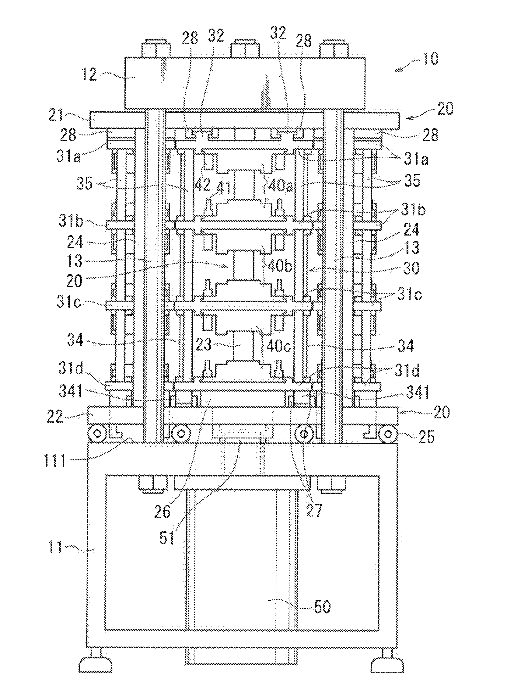
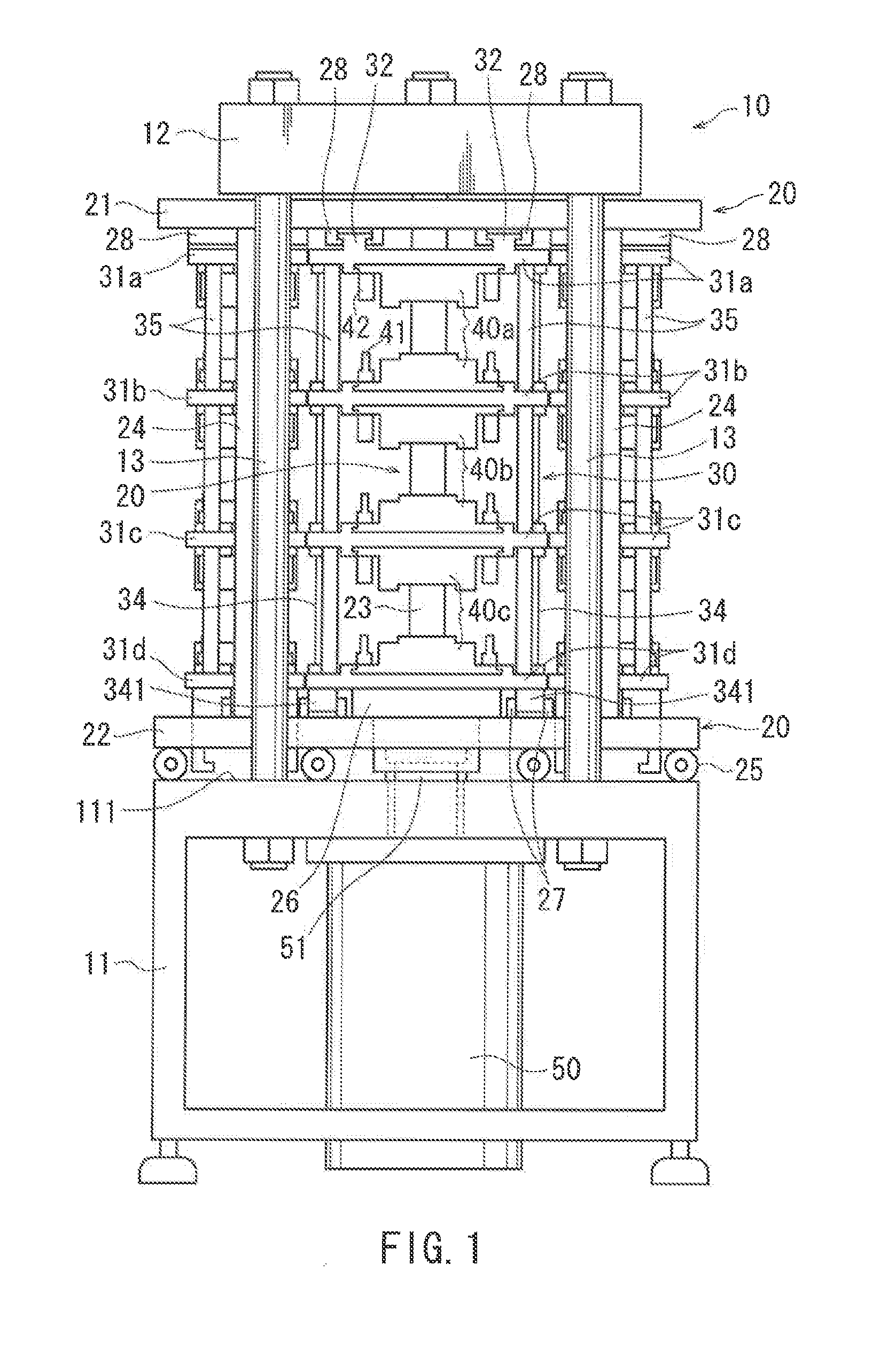
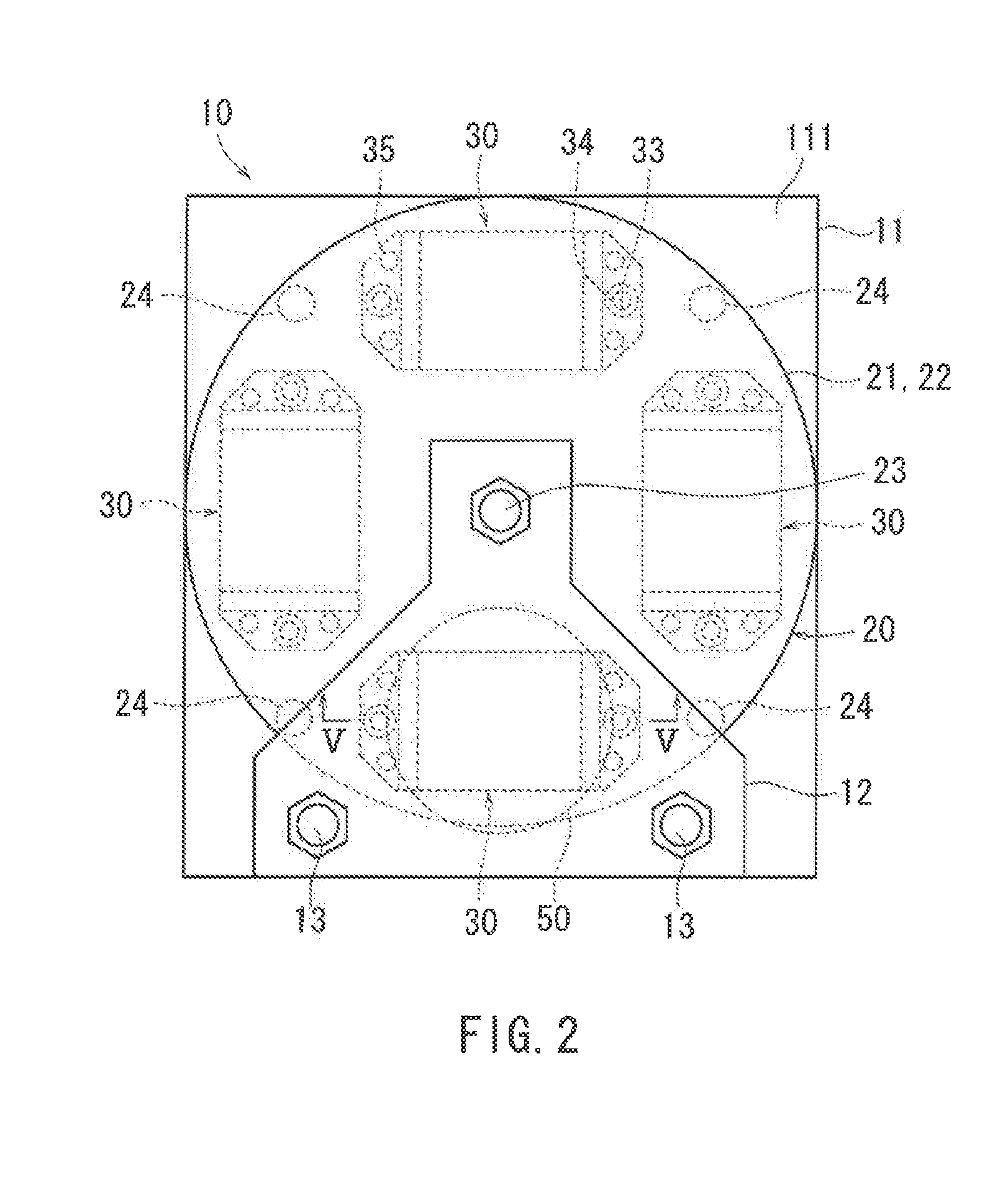
[0025]the present invention will be described with reference to the drawings. FIGS. 1 to 3 respectively show a front view, a plan view and a side view of a press 10. As shown in FIG. 1, the press 10 has a table 11 at the bottom, and a crown 12, an upper plate, at the top. A crown 12 and the table 11 are tied with two vertical struts 13 fastened by bolts. A rotation shaft 23, which will be described later, also functions as a strut, so that the crown 12 is virtually supported by the rotation shaft 23 and the struts 13.
[0026]In the center of the press 10 is provided a revolver 20 rotatable about a vertical axis. The revolver 20 has four holders 30 suspended from it. Each of the holders 30 supports three pairs of forming dies 40a, 40b and 40c in series. As shown in FIG. 3, below the top plate 111 of the table 11, there is provided with a hydraulic cylinder 50 as a driving source of press, and a servo motor 60 as a driving source for rotating the revolver 20. As shown in FIGS. 4 to 7, t...
second embodiment
[0048]the present invention has been described above. According to this embodiment, after each pressing operation is completed, the revolver 20 is rotated, the dies holding the workpieces that has been pressing process is moved to a position different from the pressing position while another holder is moved to the press position. Therefore, it is possible to carry out processing steps in the dies of another holder, without waiting for the completion of transfer of processed workpieces. Therefore, it is possible to provide a press with good production efficiency and can reduce the time required for production. According to this embodiment, processes of processing parts A, B, C and D are completed in turn one by one. Assembly process of parts may be started as soon as all kinds of parts are collected by one piece for each kind, and this can contribute to an improved efficiency in production process.
[0049]A third embodiment of the present invention will be described with reference to t...
third embodiment
[0050]A flow of producing parts A, B and C of the third embodiment will be described. For FIG. 14 (a) shows a condition in which the holder 30a in the pressing position, the holder 30b, the holder 30c, the holder 30d are arranged counterclockwise in this order. The kinds of parts A, B and C each requires four steps to produce. The production processes for these kinds of parts are assigned to the lower, middle and upper rows of dies respectively so that their final processing step belong to different holders. As shown in FIG. 15, the final steps for each part A, B and C fall in the holders b, c and d, respectively.
[0051]First, the hydraulic cylinder is controlled by the control device to carry out a pressing operation described above on the holder 30a in the pressing position as in FIG. 14(a). The workpieces Y0, X1, W2 becomes workpieces Y1, X2, W3 through the processing steps C1, B2, A3, respectively, as shown in FIG. 14 (c). During this pressing operation, the transfer device is co...
PUM
 Abstract
Description
Claims
Application Information
 - R&D
- Intellectual Property
- Life Sciences
- Materials
- Tech Scout
- Unparalleled Data Quality
- Higher Quality Content
- 60% Fewer Hallucinations
Browse by: Latest US Patents, China's latest patents, Technical Efficacy Thesaurus, Application Domain, Technology Topic, Popular Technical Reports.
© 2025 PatSnap. All rights reserved.Legal|Privacy policy|Modern Slavery Act Transparency Statement|Sitemap|About US| Contact US: help@patsnap.com


