

Heat exchanger
a technology of heat exchanger and heat exchanger plate, which is applied in the direction of indirect heat exchanger, refrigeration components, light and heating apparatus, etc., can solve the problem of unwetted tubes in the lower region
- Summary
- Abstract
- Description
- Claims
- Application Information
AI Technical Summary
Benefits of technology
Problems solved by technology
Method used
Image

Examples
second embodiment
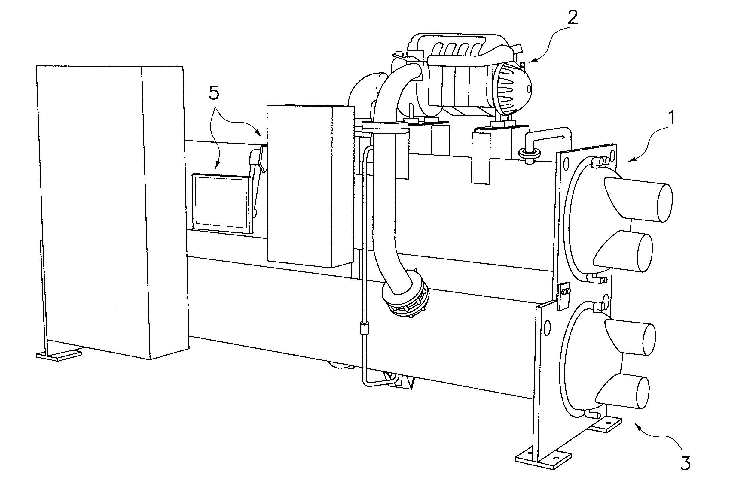
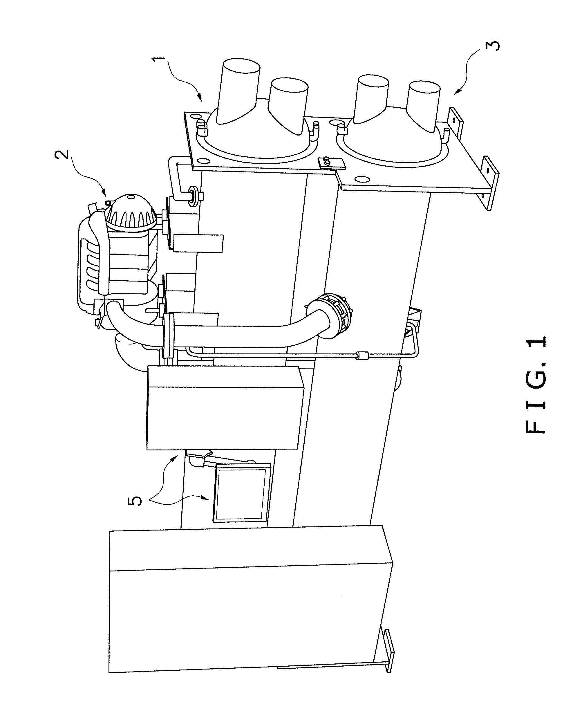
[0075]Referring now to FIGS. 14 to 19, an evaporator 101 in accordance with a second embodiment will now be explained. In view of the similarity between the first and second embodiments, the parts of the second embodiment that are identical to the parts of the first embodiment will be given the same reference numerals as the parts of the first embodiment. Moreover, the descriptions of the parts of the second embodiment that are identical to the parts of the first embodiment may be omitted for the sake of brevity.
[0076]The evaporator 101 according to the second embodiment is basically the same as the evaporator 1 of the first embodiment illustrated in FIGS. 2 to 7 except for the geometry of a tube bundle 130. In the second embodiment, the heat transfer tubes 31 are arranged such that a horizontal pitch between adjacent ones of the columns is larger in an outer region of the tube bundle 130 than in an inner region of the tube bundle 130.
[0077]More specifically, in the example shown in...
third embodiment
[0085]Referring now to FIGS. 20 to 25, an evaporator 201 in accordance with a third embodiment will now be explained. In view of the similarity between the first, second and third embodiments, the parts of the third embodiment that are identical to the parts of the first or second embodiment will be given the same reference numerals as the parts of the first or second embodiment. Moreover, the descriptions of the parts of the third embodiment that are identical to the parts of the first or second embodiment may be omitted for the sake of brevity.
[0086]The evaporator 201 according to the second embodiment is basically the same as the evaporator 1 of the first embodiment illustrated in FIGS. 2 to 7 except for the geometry of a tube bundle 230. In the third embodiment, a vertical pitch between adjacent ones of the heat transfer tubes 31 in each of the columns is set to be larger in an upper region of the tube bundle 230 than in a lower region of the tube bundle 230. In addition, a hori...
fourth embodiment
[0096]Referring now to FIGS. 26 and 27, an evaporator 301 in accordance with a fourth embodiment will now be explained. In view of the similarity between the first through fourth embodiments, the parts of the fourth embodiment that are identical to the parts of the first, second or third embodiment will be given the same reference numerals as the parts of the first, second or third embodiment. Moreover, the descriptions of the parts of the fourth embodiment that are identical to the parts of the first, second or third embodiment may be omitted for the sake of brevity.
[0097]In the evaporator 301 of the fourth embodiment, an intermediate tray part 60 is provided between the heat transfer tubes 31 in the supply line group and the heat transfer tubes 31 in the return line group. The intermediate tray part 60 includes a plurality of discharge apertures 60a through which the liquid refrigerant is discharged downwardly.
[0098]As discussed above, the evaporator 301 incorporates a two pass sy...
PUM
 Abstract
Description
Claims
Application Information