
Portable video communication device having camera, and method of performing video communication using the same

Inactive Publication Date: 2013-10-24
ELECTRONICS & TELECOMM RES INST
View PDF20 Cites 4 Cited by
  • Summary
  • Abstract
  • Description
  • Claims
  • Application Information

AI Technical Summary

Benefits of technology

The present invention relates to video communication devices and methods that can solve the problem of discrepancies between the sight lines of users during video calls. This invention provides a viewpoint synthesis image that allows multiple users to communicate while aligning their sight lines, creating a more seamless video communication experience. Additionally, the invention allows for the creation of stereoscopic images to further enhance the video communication experience. The invention also adapts to user requests and changes in communication environments, providing a more convenient and improved video communication service.

Problems solved by technology

However, a video communication service using a third generation (3G) network has low user satisfaction due to low image quality, and when the video communication service uses a Wi-Fi network, degradation of image quality is somewhat solved, but a problem of discrepancy between sight lines of a user still exists.
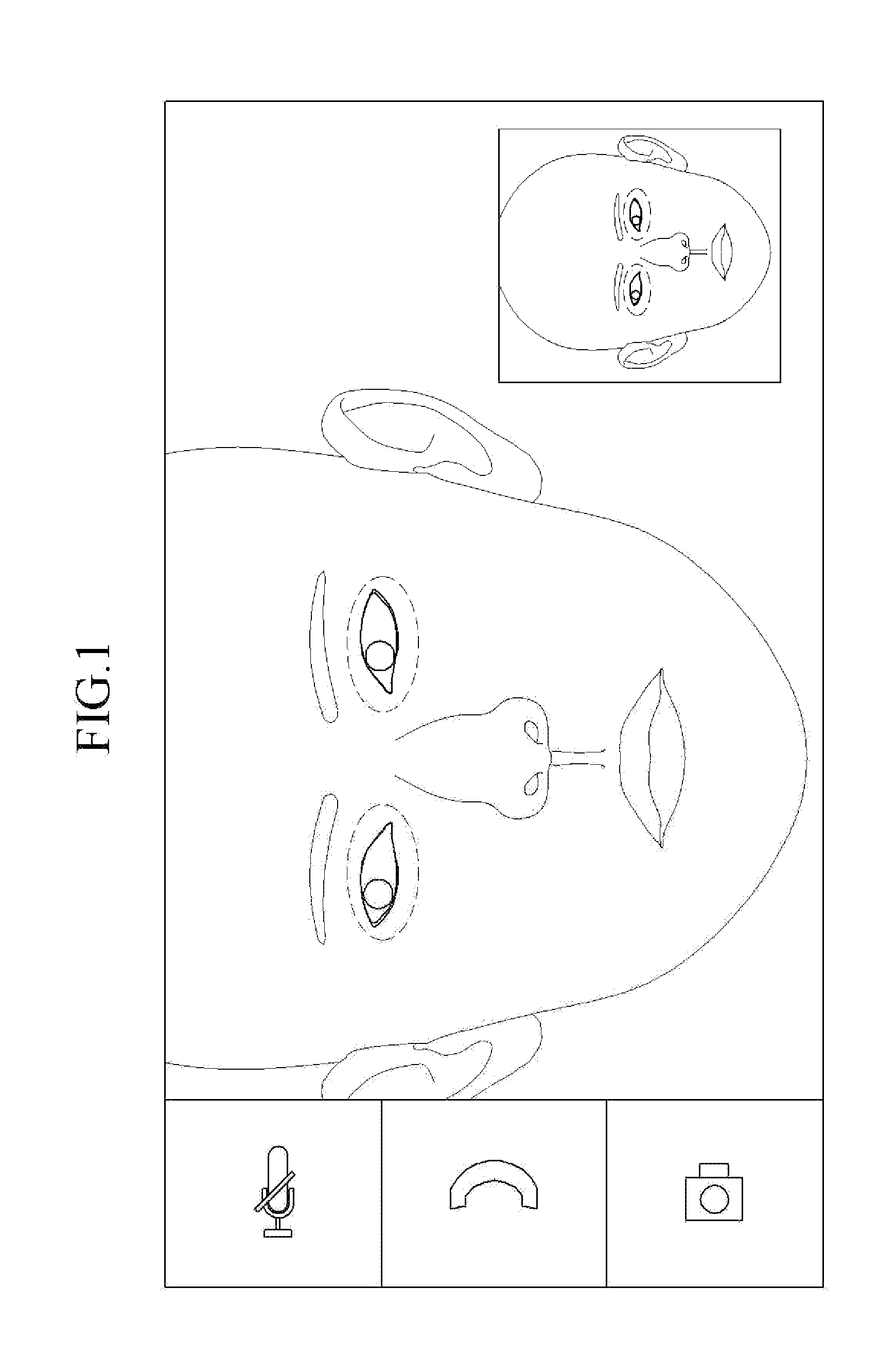
The problem of discrepancy between sight lines indicates a discrepancy between a sight line in which a user views a video communication terminal and a user's sight line that is displayed on a screen of a video communication terminal.
Therefore, both parties performing video communication view the center of the screen, but there is a problem that a sight line of either one of both parties does not correspond with that of the other one.
Further, the conventional video communication device cannot perform a mode change between video communication and audio communication before starting an incoming call or while performing communication.
Therefore, even if a poor communication environment and insufficient system resources are a problem, by continuing to maintain a presently set communication mode, the conventional video communication device insufficiently copes with a problem that communication quality is entirely deteriorated.

Method used


Image

  • Portable video communication device having camera, and method of performing video communication using the same
  • Portable video communication device having camera, and method of performing video communication using the same
  • Portable video communication device having camera, and method of performing video communication using the same

Examples


Embodiment Construction

[0040]In the following detailed description, only certain exemplary embodiments of the present invention have been shown and described, simply by way of illustration. As those skilled in the art would realize, the described embodiments may be modified in various different ways, all without departing from the spirit or scope of the present invention. Accordingly, the drawings and description are to be regarded as illustrative in nature and not restrictive. Like reference numerals designate like elements throughout the specification.

[0041]In addition, in the entire specification, unless explicitly described to the contrary, the word “comprise” and variations such as “comprises” or “comprising” will be understood to imply the inclusion of stated elements but not the exclusion of any other elements.

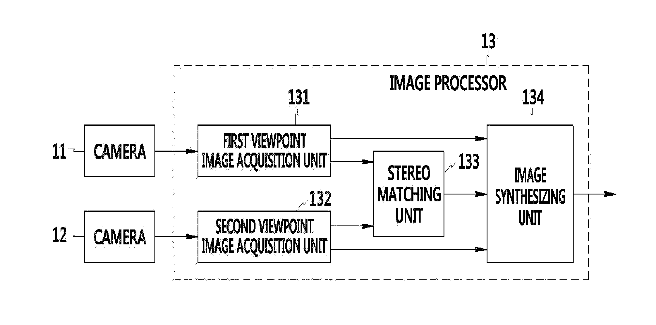
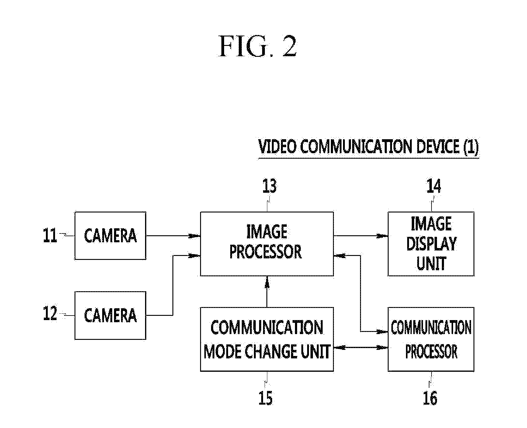
[0042]Hereinafter, a video communication device and a method of controlling the same according to an exemplary embodiment of the present invention will be described with reference to the atta...


PUM


Abstract

A video communication device includes a first camera and a second camera that are positioned at different positions to form a symmetrical relationship about a reference point at a periphery of a video display screen. The video communication device performs video communication based on images that are acquired from the first camera and the second camera, and performs a communication mode change according to a request for a communication mode change.

Description

TECHNICAL FIELD[0001]The present invention relates to a video communication device. More particularly, the present invention relates to a portable video communication device having a camera, and a method of performing video communication using the same.BACKGROUND ART[0002]With an increase of available bandwidth of a mobile communication service and an increase in the spread of Wi-Fi, services for providing video communication in an individual portable device have gradually increased. However, a video communication service using a third generation (3G) network has low user satisfaction due to low image quality, and when the video communication service uses a Wi-Fi network, degradation of image quality is somewhat solved, but a problem of discrepancy between sight lines of a user still exists.[0003]The problem of discrepancy between sight lines indicates a discrepancy between a sight line in which a user views a video communication terminal and a user's sight line that is displayed on...

Claims


Application Information

Patent Timeline
IPC IPC(8): H04N13/02H04N13/239
CPCH04N13/0282H04N7/14H04N13/289H04N13/194H04N13/239H04N13/282
Inventor CHOI, MIN SHEO
Owner ELECTRONICS & TELECOMM RES INST
Learn More