Print control device and print control method

a control device and control method technology, applied in the direction of digital output to print units, digitally marking record carriers, instruments, etc., can solve the problem of difficult to uniformly provide high gloss over the whole sheet of paper on which an image is formed with clear toner

a control device and control method technology, applied in the direction of digital output to print units, digitally marking record carriers, instruments, etc., can solve the problem of difficult to uniformly provide high gloss over the whole sheet of paper on which an image is formed with clear toner

US20130278943A1Inactive Publication Date: 2013-10-24RICOH KK

Image

  • Print control device and print control method
  • Print control device and print control method
  • Print control device and print control method

Examples


Embodiment Construction

[0048]Hereinafter, an embodiment of a print control device, a print control method, and a computer-readable recording medium including a program will be described in detail with reference to the appended drawings.

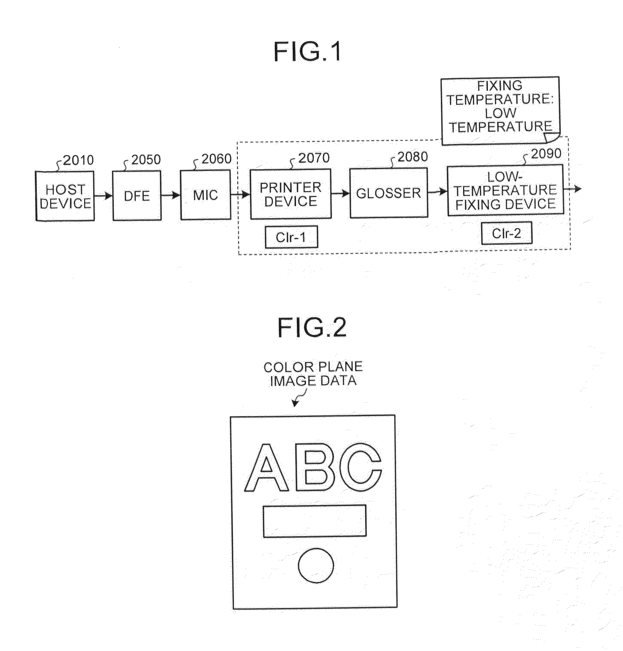
[0049]First, a configuration of an image forming system according to a present embodiment will be described with reference to FIG. 1. In the present embodiment, the image forming system is configured such that a printer control device (DFE: Digital Front End) 2050 (hereinafter, referred to as “DFE 2050”), an interface controller (MIC: Mechanism I / F Contoroller) 2060 (hereinafter, referred to as “MIC 2060”), a printer device 2070, and a glosser 2080 and a low-temperature fixing device 2090 as a post-processing devices are connected. The DFE 2050 communicates with the printer device 2070 via the MIC 2060, and controls formation of an image in the printer device 2070. Also, the DFE 2050 is connected with a host device 2010 such as a personal computer (PC), and the DFE 2050 rec...


PUM


Abstract

An inverse image data generating unit that generates inverse image data that indicates a transparent developer amount that indicates an amount of a transparent developer, and a region where the transparent developer amount is used, based on a color plane image data that indicates a color developer amount that indicates an amount of a color developer, and a region where the color developer amount is used; a conversion unit that converts the transparent developer amount of the inverse image data into a transparent developer amount larger than the transparent developer amount by referring to a conversion table; and a transparent developer plane image data generating unit that generates transparent developer plane image data used in image formation of a transparent developer in an image forming apparatus based on the inverse image data indicating a transparent developer amount after the conversion.

Description

CROSS-REFERENCE TO RELATED APPLICATIONS[0001]The present application claims priority to and incorporates by reference the entire contents of Japanese Patent Application No. 2012-095168 filed in Japan on Apr. 18, 2012.BACKGROUND OF THE INVENTION[0002]1. Field of the Invention[0003]The present invention relates to a print control device and a print control method.[0004]2. Description of the Related Art[0005]In the past, there have been image forming apparatuses that incorporates a clear toner therein, in addition to CMYK four-color toners, the clear toner being a colorless toner that does not contain color materials. A toner image formed by the clear toner is fixed on a recording medium, such as a transfer paper, on which an image by the CMYK toners is formed. As a result, a visual effect or a tactile effect (called a surface effect) is realized on the recording medium. As a technology related to a clear toner, Japanese Patent No. 3518257 discloses a technology that uniformly reproduc...

Claims


Application Information

Patent Timeline
24 Oct 2013
Publication
US20130278943A1
IPC
G06F3/12
CPC
G03G15/0121; G06K15/1867; G06K15/129; G03G15/6585
Inventors
KUROSAWA, MASANORI; SUZUKI, HIROAKI