Control and provisioning in a data center network with at least one central controller

a data center network and central controller technology, applied in the field of data center network architectures and switching technologies, can solve the problems of excessive delay in data communication between servers that are not co-located within the same rack, and inability to control the data center network. , to achieve the effect of reducing physical interconnectivity requirements, enhancing overall application program performance, and efficient allocation of bandwidth

Active Publication Date: 2013-10-24
HEWLETT-PACKARD ENTERPRISE DEV LP
View PDF9 Cites 31 Cited by
  • Summary
  • Abstract
  • Description
  • Claims
  • Application Information

AI Technical Summary

Benefits of technology

[0009]In accordance with the present disclosure, data center networks are disclosed that can employ optical network topologies and optical nodes to efficiently allocate bandwidth within the data center networks, while reducing the physical interconnectivity requirements of the data center networks. Such data center networks employ at least one central controller for controlling and provisioning computing resources within the data center networks based at least in part on the network topology and an application component topology, thereby enhancing overall application program performance.
[0014]Using at least the information pertaining to the network topology and the affinity topology, the affinity-network topology calculator is operative to form or otherwise obtain an affinity-network topology that takes into account both the network topology and the affinity topology. The affinity-network topology is a topology model that represents a combination of the network topology and the affinity topology, which can be obtained by logically combining, e.g., by logically stitching together or overlaying, the network and affinity topologies. For example, the affinity-network topology calculator may logically stitch together the network and affinity topologies by binding affinity elements to their counterparts in the network topology, yielding one or more logical links between the affinity groups / elements and the physical and / or virtualized elements within the data center network architecture. The central controllers are operative to receive information pertaining to the affinity-network topology, and, based at least on the received information, to control one or more optical nodes, and zero, one, or more optical junction nodes, to modify the network topology, as appropriate, for implementing the affinity-network topology within the data center network, thereby providing enhanced levels of application program performance and network utilization.
[0016]Such candidate forwarding paths and trees, along with appropriate mapping functions for each optical node, can define a general framework for achieving a desired data packet forwarding behavior. Such a general framework can provide for the aggregation of addresses and affinity flows by having multiple addresses / flows map to a single candidate forwarding path or tree. Moreover, the lists of candidate forwarding paths and trees can provide a convenient way of granular load balancing by assuring that all of the optical nodes are provisioned with the same lists of candidate forwarding paths / trees, using a consistent mapping function (e.g., a hash function). In addition, the optical nodes can use the lists of candidate forwarding paths and trees to autonomously switch from active forwarding paths / trees to backup forwarding paths / trees.
[0017]Because there can be up to several hundreds of thousands, if not more, unique addresses and affinity flows in a typical data center network, it may be problematic for a central controller to provision candidate forwarding paths / trees for each destination address or affinity flow within the network. In an exemplary aspect, to avoid having to provision such a potentially large number of candidate forwarding paths / trees to each optical node in the data center network, the central controller can define what is referred to herein as an “abstract endpoint” for each optical node communicably coupled thereto. Specifically, the central controller can map appropriate source / destination abstract endpoint pairs to the respective candidate forwarding paths, and further map appropriate destination abstract endpoints to the respective candidate forwarding trees, without having to directly map the numerous individual MAC addresses and network traffic flows.
[0018]In another aspect, a controller for computing and provisioning one or more forwarding topologies in a network for enhanced application program performance and network utilization includes a topology fitting engine. The network has an associated topology and a current network state, which, as employed herein, pertains to the operational status of all of the network segments in the network and the sources and destinations to which that operational status relates, as well as the endpoint addresses (such as MAC or IP addresses) of all of the host computers communicably coupled to the respective nodes on the network. A “network segment” is defined herein as a unidirectional link in the network from a source to a destination considered at the applicable OSI model layer, e.g., layer-1, layer-2, or layer-3. The topology associated with the network includes a network topology and an affinity topology, which specifies policies and attributes that describe communications between a plurality of application components. The topology fitting engine is operative to receive information pertaining to at least an affinity-network topology that represents a logical combination of the network topology and the affinity topology, and to compute one or more forwarding topologies based at least in part on the affinity-network topology. Each forwarding topology identifies one or more network segments for forwarding traffic through the network. The topology fitting engine is further operative to provide the forwarding topologies for use in deterministically arriving at a consistent end-to-end forwarding configuration for the network as a function of the current network state.
[0019]In a further aspect, a method of computing and provisioning one or more forwarding topologies in a network for enhanced application program performance and network utilization includes receiving, at a controller, information pertaining to at least an affinity-network topology, and computing, by the controller, one or more forwarding topologies based at least in part on the affinity-network topology. The method further includes providing, by the controller, the forwarding topologies for use in deterministically arriving at the consistent end-to-end forwarding configuration for the network as a function of the current network state.

Problems solved by technology

Although conventional data center networks like those described above have been employed to satisfy the operational requirements of many university, government, business, and financial service entities, such conventional data center networks have drawbacks.
For example, data communications between servers that are not co-located within the same rack may experience excessive delay (also referred to herein as “latency”) within the data center networks, due to the multitude of switches and / or routers that the data may be required to traverse as it propagates “up”, “down”, and / or “across” the hierarchical architecture of the networks.
Data communications between such servers may also experience latency within the respective switches and / or routers of the data center networks due to excessive node and / or link utilization.
Further, because multiple paths may be employed to deliver broadcast and / or multicast data to different destinations within the data center networks, such broadcast and / or multicast data may experience excessive latency skew.
Such latency and / or latency skew may be exacerbated as the sizes of the data center networks and / or their loads increase.
However, such configuration data frequently lack contextual information, such as how the topology of a data center network should be configured in view of the available computing resources to achieve a desired level of application performance.
However, the OVF standard generally lacks contextual information pertaining to the network topology, and may therefore be incapable of assuring that the available computing resources are being properly provisioned for the desired application performance level.
As a result, problems with latency, data bottlenecks, etc., may be further exacerbated, thereby slowing down or otherwise inhibiting data movement within the data center networks.

Method used


Image

  • Control and provisioning in a data center network with at least one central controller
  • Control and provisioning in a data center network with at least one central controller
  • Control and provisioning in a data center network with at least one central controller

Examples


Embodiment Construction

[0040]The disclosures of U.S. patent application Ser. No. ______ filed ______, 2012 entitled DATA CENTER NETWORK ARCHITECTURE (attorney docket no. PLEX-004XX), U.S. patent application Ser. No. ______ filed ______, 2012 entitled AFFINITY MODELING IN A DATA CENTER NETWORK (attorney docket no. PLEX-005XX), U.S. patent application Ser. No. ______ filed ______, 2012 entitled HIERARCHY OF CONTROL IN A DATA CENTER NETWORK (attorney docket no. PLEX-007XX), U.S. Provisional Patent Application No. 61 / 554,107 filed Nov. 1, 2011 entitled DATA CENTER NETWORK SWITCHING, U.S. patent application Ser. No. 13 / 528,501 filed Jun. 20, 2012 entitled OPTICAL ARCHITECTURE AND CHANNEL PLAN EMPLOYING MULTI-FIBER CONFIGURATIONS FOR DATA CENTER NETWORK SWITCHING, and U.S. patent application Ser. No. 13 / 528,211 filed Jun. 20, 2012 entitled OPTICAL JUNCTION NODES FOR USE IN DATA CENTER NETWORKS, are incorporated herein by reference in their entirety.

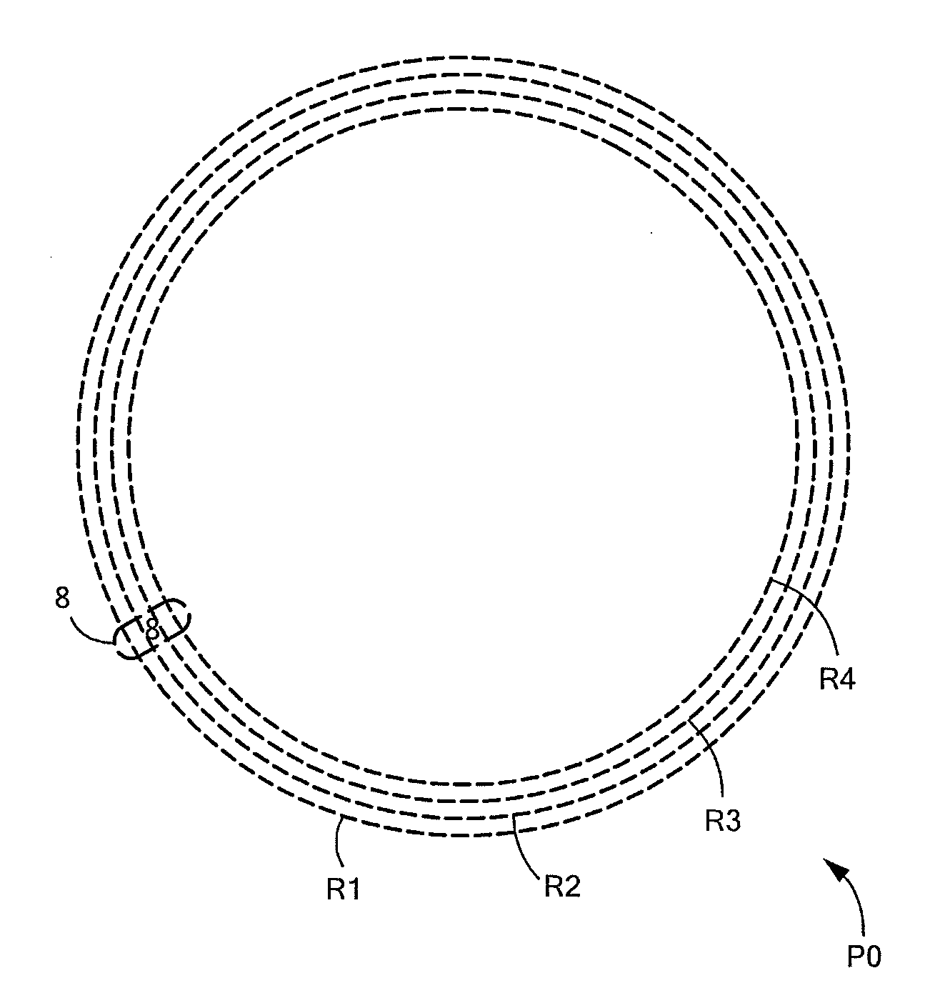
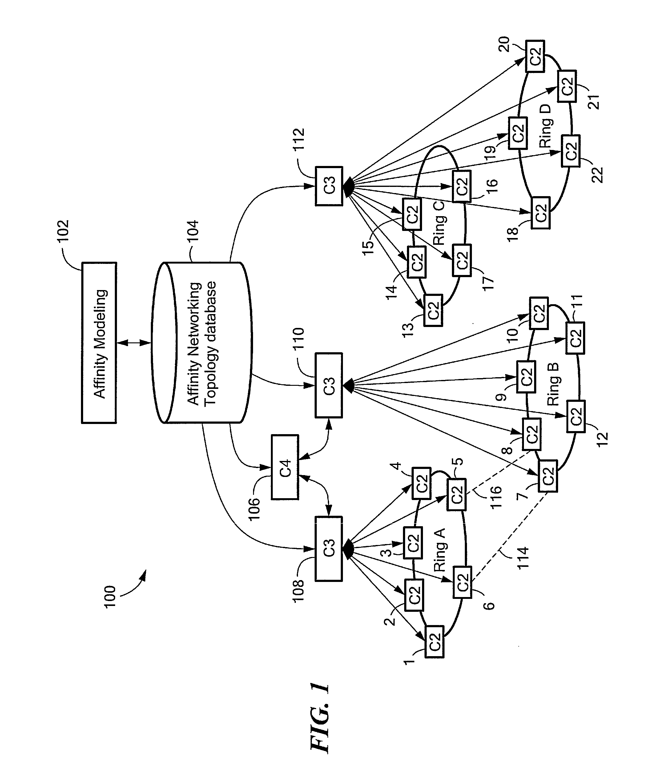
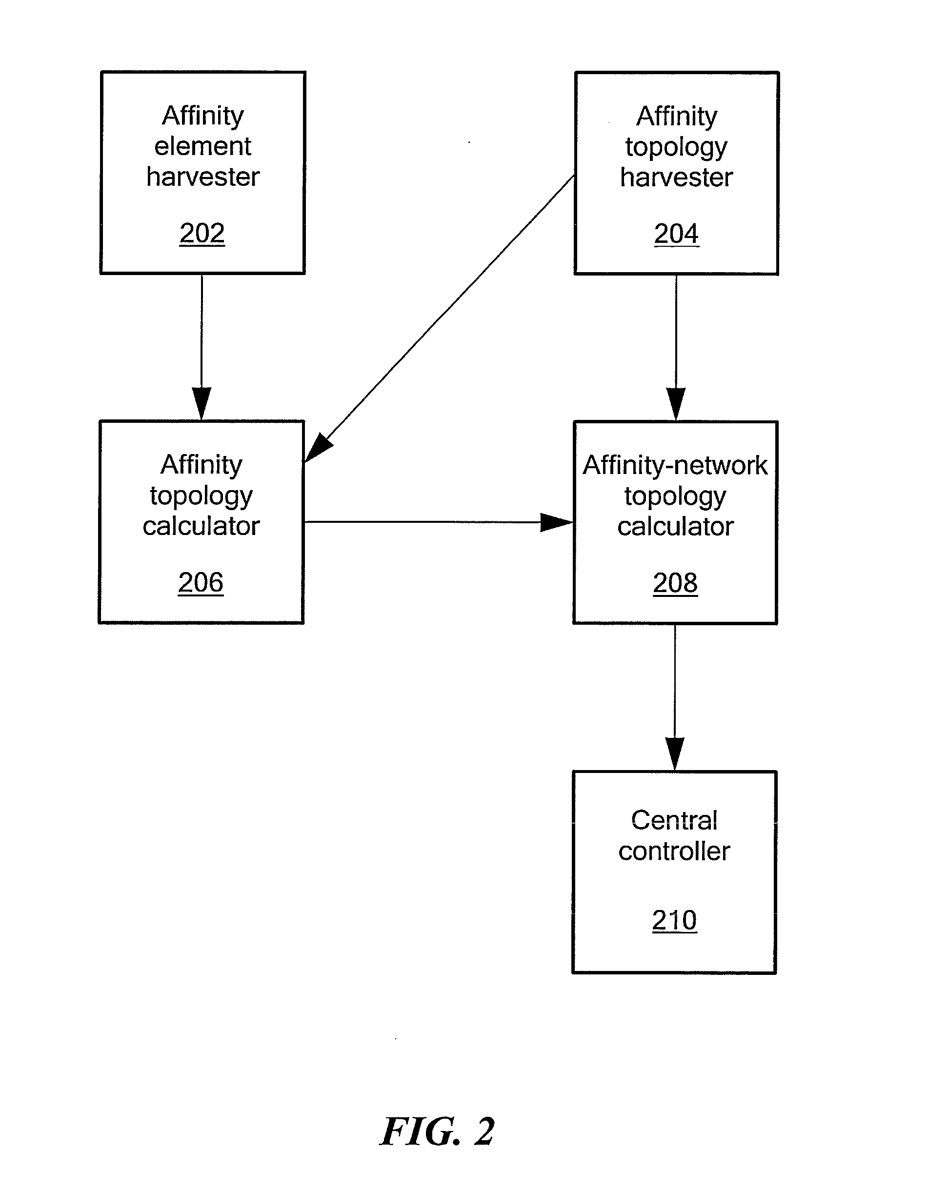
[0041]Data center networks are disclosed that can employ optica...


PUM


Abstract

Data center networks that employ optical network topologies and optical nodes to efficiently allocate bandwidth within the data center networks, while reducing the physical interconnectivity requirements of the data center networks. Such data center networks employ at least one central controller for controlling and provisioning computing resources within the data center networks based at least in part on the network topology and an application component topology, thereby enhancing overall application program performance.

Description

CROSS REFERENCE TO RELATED APPLICATIONS[0001]This application claims benefit of the priority of U.S. Provisional Patent Application No. 61 / 554,107 filed Nov. 1, 2011 entitled DATA CENTER NETWORK SWITCHING. This application is a continuation-in-part of U.S. patent application Ser. No. 13 / 528,501 filed Jun. 20, 2012 entitled OPTICAL ARCHITECTURE AND CHANNEL PLAN EMPLOYING MULTI-FIBER CONFIGURATIONS FOR DATA CENTER NETWORK SWITCHING, and a continuation-in-part of U.S. patent application Ser. No. 13 / 528,211 filed Jun. 20, 2012 entitled OPTICAL JUNCTION NODES FOR USE IN DATA CENTER NETWORKS.STATEMENT REGARDING FEDERALLY SPONSORED RESEARCH OR DEVELOPMENT[0002]—Not applicable—FIELD OF THE INVENTION[0003]The present disclosure relates generally to data center network architectures and switching technologies, and more specifically to data center networks that employ optical network topologies and optical nodes to efficiently allocate bandwidth within the data center networks, while reducing ...

Claims


Application Information

Patent Timeline
Patent Type & Authority Applications(United States)
IPC IPC(8): H04B10/27
CPCH04B10/27H04Q11/0062H04Q2011/009H04Q3/0095H04Q2213/13106H04L45/12
Inventor SRINIVAS, ANANDDERUIJTER, DENIS H.HUSAK, DAVID J.
Owner HEWLETT-PACKARD ENTERPRISE DEV LP
Why Eureka
Try Eureka