Apparatus, system and method to account for spherical aberration at the iris plane in the design of an intraocular lens

a technology of iris plane and iris plane, applied in the field of intraocular lens design, can solve the problems of not being able to provide post-operative spherical aberration compensation with available lenses, not being able to meet the needs of patients with postlasik eyes, and not being able to achieve the effect of improving visual outcomes

Active Publication Date: 2013-10-24
AMO GRONINGEN
View PDF1 Cites 27 Cited by
  • Summary
  • Abstract
  • Description
  • Claims
  • Application Information

AI Technical Summary

Problems solved by technology

Unfortunately, the SRK regression formula may yield inadequate indications, which has led to the development of the SRKII and SRK / T formulae.
Current power calculation procedures are paraxial and by definition do not account for spherical aberration present in cornea and IOL.
Ray tracing procedures include wavefront aberrations but this is not a common tool in current clinical practice.
Available lenses typically do not provide post-operative spherical aberration compensation for patients having non-average eye characteristics prior to implantation.
For example, the post-lasik eye may have characteristics that are difficult to measure due to the surgical modifications to the eye, and it is well understood that these surgical modifications to the post-lasik eye, such as the decoupling that occurs between the anterior and posterior corneal radius after lasik, make certain of the eye characteristics calculated for “average” patients inaccurate for postlasik eyes.
Thus, it is well known that it is exceedingly difficult to provide a recommended IOL having characteristics that will produce the desired refractive outcome and residual ocular spherical aberration for post-lasik patients.
More particularly, for example, it has been widely reported that standard lasik procedure may typically generate large amounts of corneal aberrations.

Method used


Image

  • Apparatus, system and method to account for spherical aberration at the iris plane in the design of an intraocular lens
  • Apparatus, system and method to account for spherical aberration at the iris plane in the design of an intraocular lens
  • Apparatus, system and method to account for spherical aberration at the iris plane in the design of an intraocular lens

Examples


Embodiment Construction

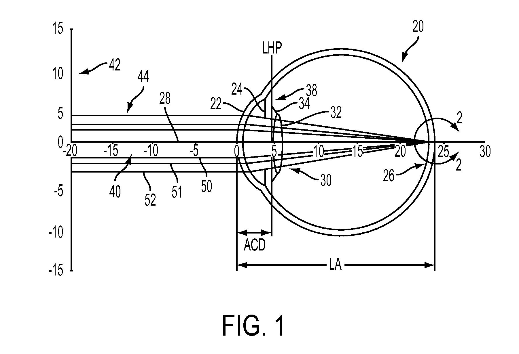
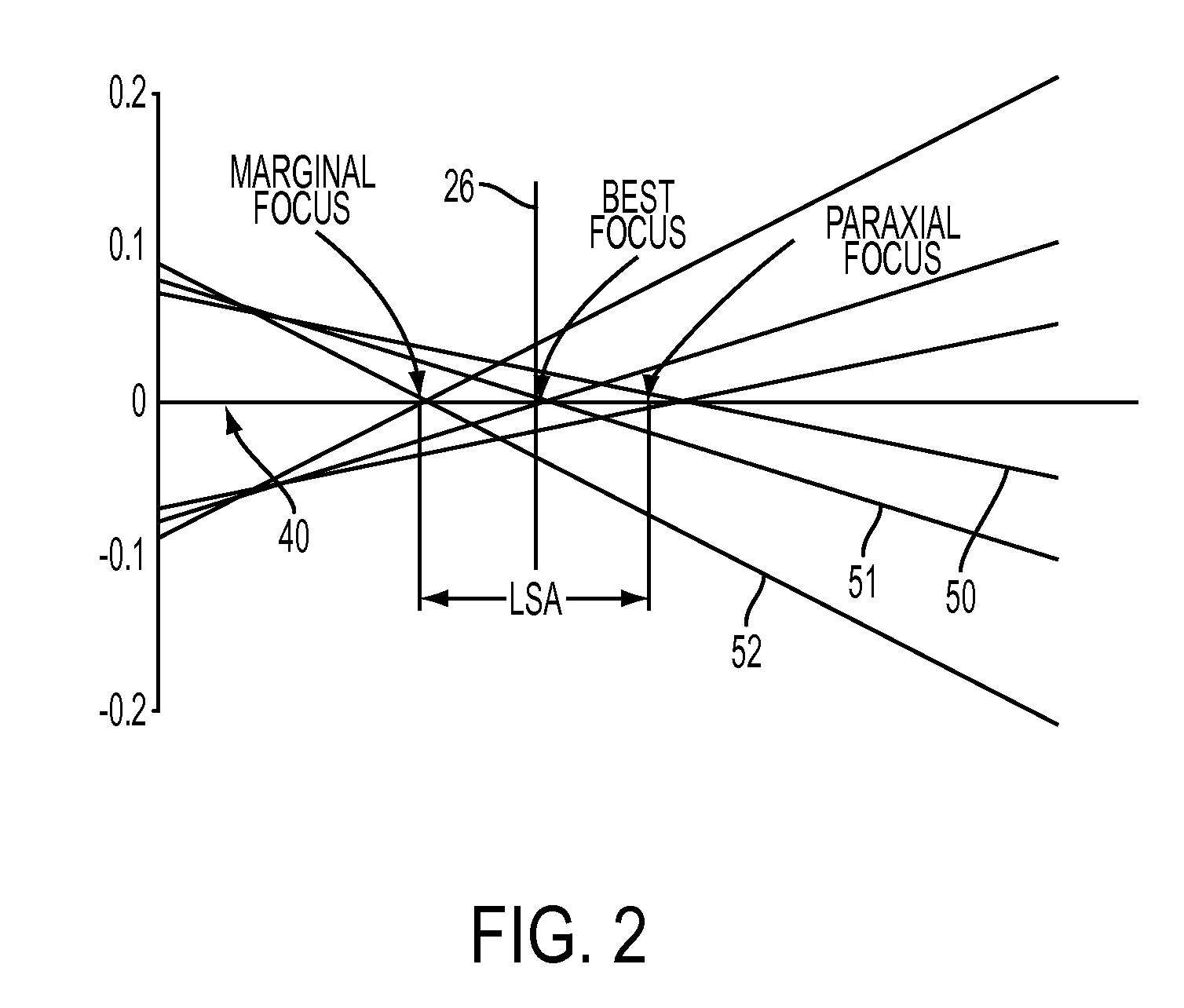
[0037]It is to be understood that the figures and descriptions of the present invention have been simplified to illustrate elements that are relevant for a clear understanding of the present invention, while eliminating, for the purpose of clarity and brevity, many other elements found in typical implantable optic apparatuses, systems and methods. Those of ordinary skill in the art may thus recognize that other elements and / or steps are desirable and / or required in implementing the present invention. However, because such elements and steps are well known in the art, and because they do not facilitate a better understanding of the present invention, a discussion of such elements and steps is not provided herein. The details of the present invention are provided with respect to the figures referenced herein, and further with respect to Appendix A, attached hereto, in which appendices certain additional details of the present invention are provided with reference to the description im...


PUM


Abstract

The present invention includes at least an intraocular lens, and a system and method of customizing at least one characteristic for an intraocular lens, in accordance with a regression that indicates the postoperative spherical aberration at the iris plane of a patient aphakic eye, in order to obtain a desired postoperative condition. The lens, system and method of customizing at least one characteristic of an intraocular lens may include measuring at least one biometric parameter of an eye at a desired light level, determining a desired postoperative condition of the eye, obtaining a corneal spherical aberration and an anterior chamber depth of the eye, and empirically calculating a spherical aberration at an iris or pupil plane of the eye, based on a regression formula comprising at least the corneal spherical aberration and the anterior chamber depth, and cross products thereof.

Description

CROSS-REFERENCES TO RELATED APPLICATIONS[0001]This patent application claims priority to U.S. provisional patent application 61 / 547,454 filed on Oct. 14, 2011 and U.S. provisional patent application 61 / 642,649 filed on May 4, 2012, the entire contents of both of which are incorporated herein by reference for all purposes as if fully set forth herein.FIELD OF THE INVENTION[0002]The present invention relates generally to the design of intraocular lenses (IOLs) and, more particularly, is directed to an apparatus, system and method to account for spherical aberration at the iris plane in the design and selection of an intraocular lens.BACKGROUND OF THE INVENTION[0003]Intraocular Lenses (IOLs) are frequently used for restoring or improving visual performance, such as after cataract surgery. Because an IOL may be selected from various providers and with differing IOL characteristics, reliable systems and methods to select IOLs having IOL characteristics that achieve the desired refractive...

Claims


Application Information

Patent Timeline
Patent Type & Authority Applications(United States)
IPC IPC(8): A61F2/16G02C7/02
CPCA61F2/16G02C7/024A61B3/1005A61F2240/002A61B3/0025A61F2/1637A61F9/007
Inventor VAN DER MOOREN, MARRIE H.PIERS, PATRICIA ANNBOGAERT, THEOPHILUSNORRBY, SVERKERCANOVAS-VIDAL, CARMEN
Owner AMO GRONINGEN
Why Eureka
Try Eureka