
Method for Repairing Metallic Structure

a technology of metallic structure and repair method, which is applied in the direction of manufacturing tools, railway track construction, roads, etc., to achieve the effect of allowing more time for the running of revenue-producing trains and more time efficient tim

Inactive Publication Date: 2013-10-31
HOLLAND CO
View PDF25 Cites 5 Cited by
  • Summary
  • Abstract
  • Description
  • Claims
  • Application Information

AI Technical Summary

Benefits of technology

[0026]Because the rail repair is accomplished without using a rail plug, there is no need to transport rail plugs to or away from the repair site. Additionally, the NRT of the original rail is maintained as no additional rail or materials are or even can be added or removed from the existing rail length. Because only a single weld is required, and the insertion of a rail plug is not required (as compared to other prior methods requiring two welds and plug exchange), the disclosed repair method is more time efficient than prior repair methods.
[0027]Given that the repair method is typically faster and does not require additional rail or materials, this method of repair can be performed instead of using a joint bar splice. The repair can be accomplished in the same track occupation as required by the detector car, thereby allowing more time of the running of revenue-producing trains. Moreover, the material characteristics and the process used to deposit the fill material can provide a repair structure which has the properties equaling those of the rail material and far surpassing those of the thermite weld.

Problems solved by technology

Additionally, manual testing of the defect may further delineate the areas of the rail that contains the defect.

Method used


Image

  • Method for Repairing Metallic Structure
  • Method for Repairing Metallic Structure
  • Method for Repairing Metallic Structure

Examples


Embodiment Construction

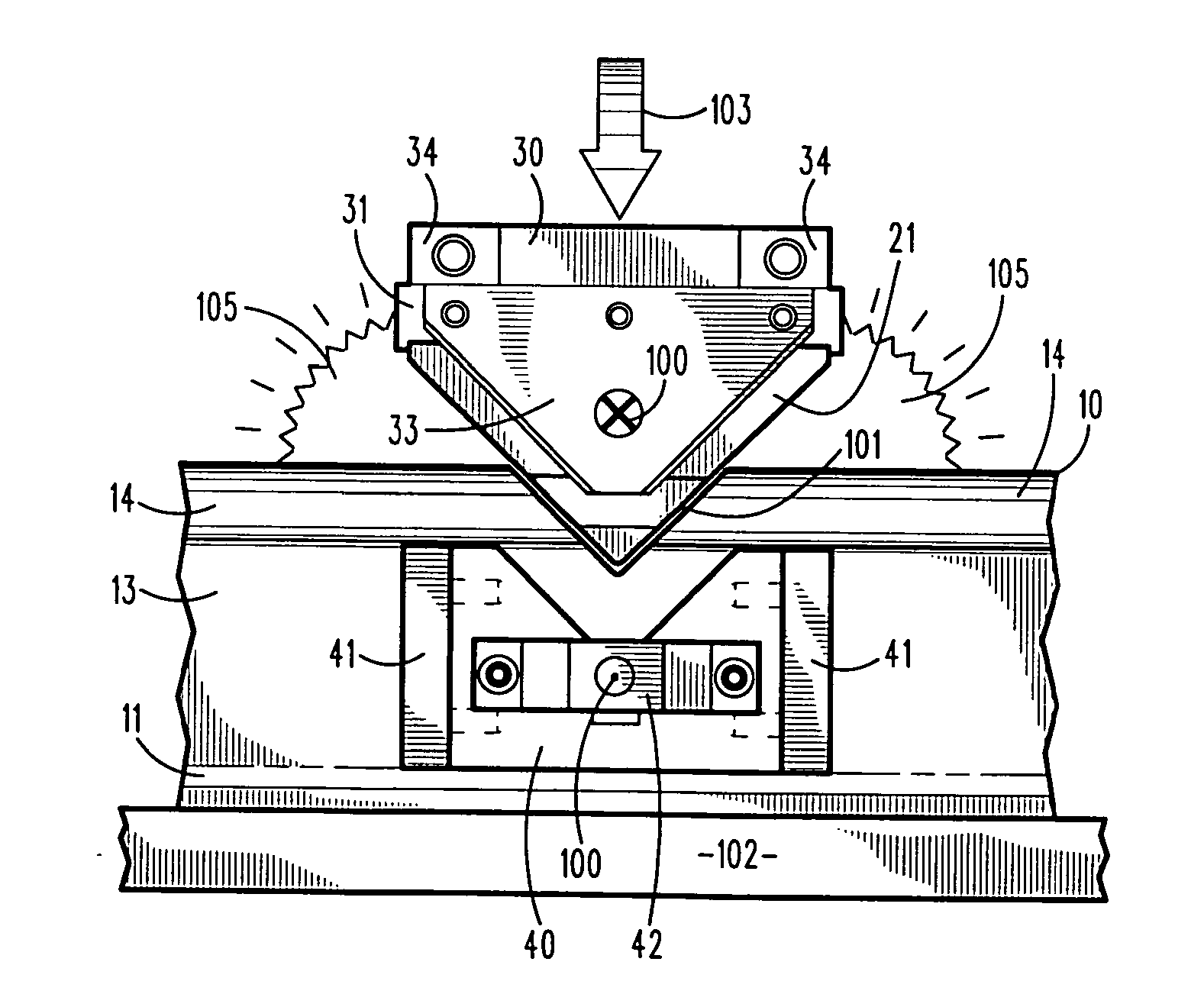
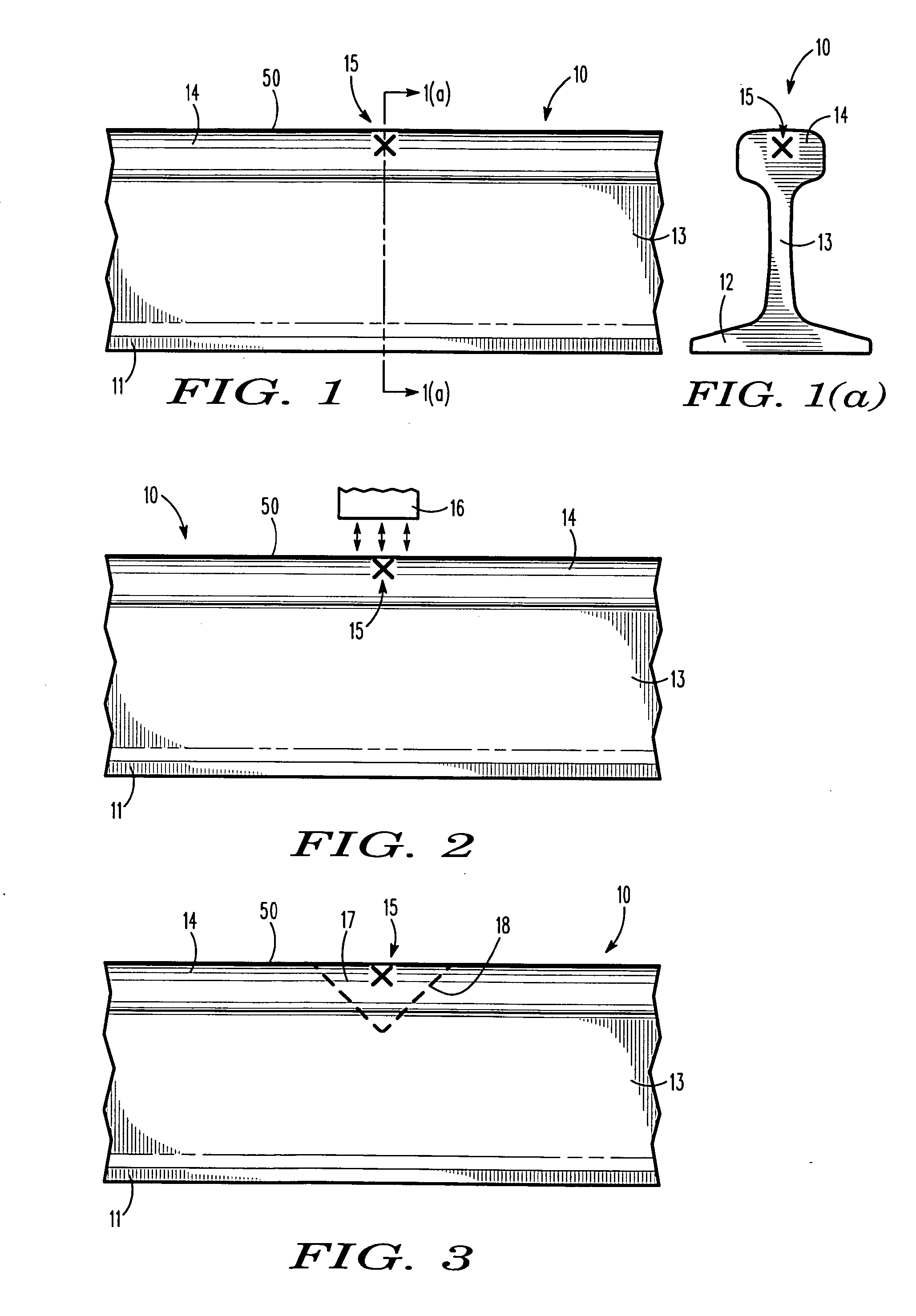
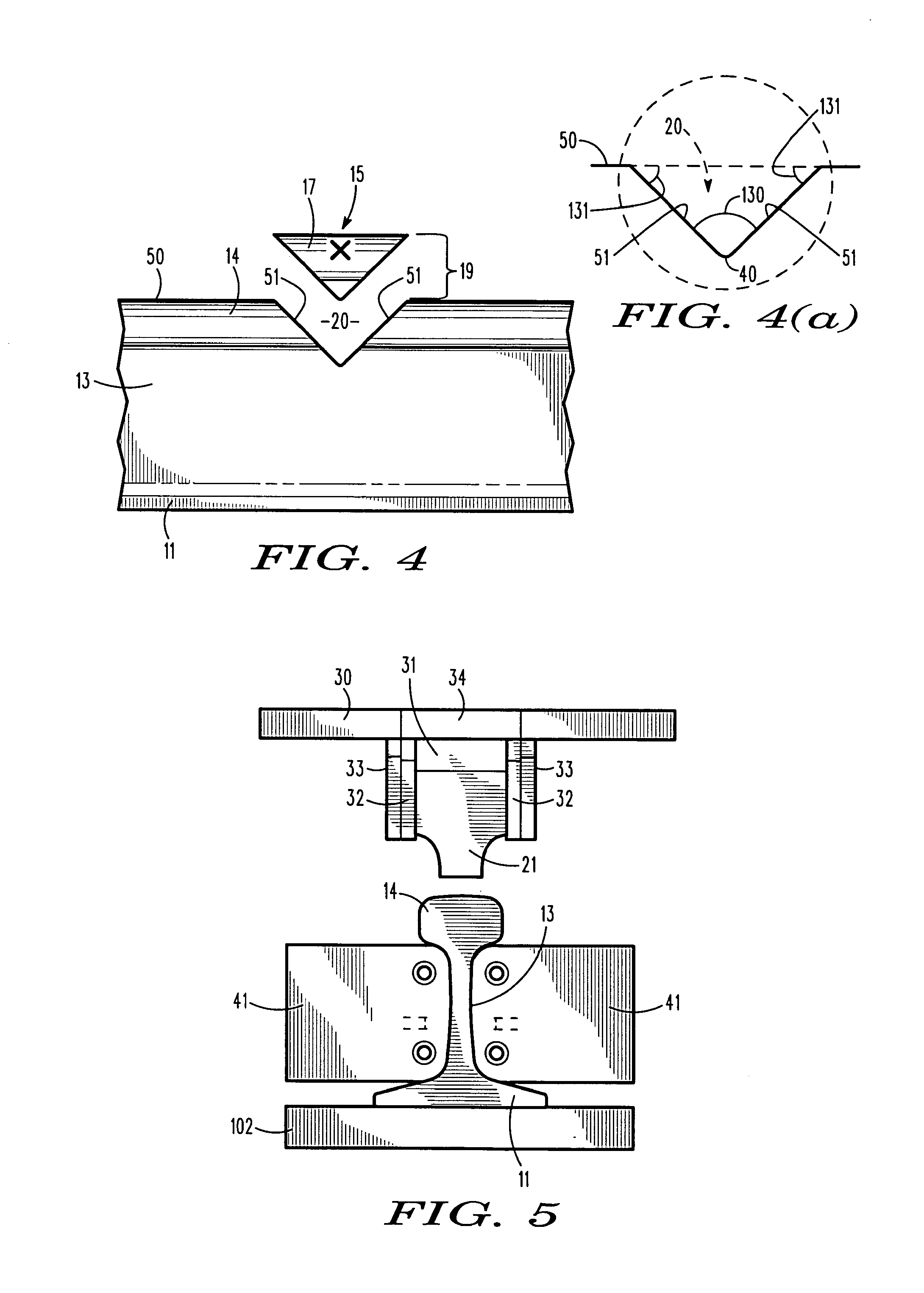
[0052]Referring now to the drawings with more specificity, the reader is directed to FIG. 1, which figure depicts a side elevational view of a fragmentary rail section or length as referenced at 10. A rail length 10 is typically formed having a rail base portion 11 with opposed flanges 12, an upstanding rail web portion 13 extending upward from the base portion 11 between the flanges 12, and a rail head portion 14 at the top of the rail web portion 13 as generally and comparatively depicted in FIGS. 1 and 1(a).

[0053]The repair system or method according to the present invention effectively begins when a rail defect 15 is identified and located, such as by way of ultrasonic rail-testing. Ultrasonic rail-testing can precisely locate and mark the area of rail 10 containing the defect 15. Additionally, manual testing of the defect 15 may further delineate the areas of the rail 10 which contain the defect 15. The ultrasonic testing, as exemplary defect locating means, can further confirm...


PUM

PropertyMeasurementUnit
angleaaaaaaaaaa
lengthaaaaaaaaaa
lengthaaaaaaaaaa

Abstract

A rail repair method enables repair of rails and rail-like structures. A rail defect is initially identified and removed as contained within a volumetric material portion so as to form a contoured void while maintaining continuity of the rail opposite the void. A pre-formed insert is then placed into the void thereby effecting a rail-to-insert interface. Current is driven through the interface as force directs the insert against the rail. Resistance heat and pressure weld the insert to the rail. The flash welding aspects remove oxides and other impurities from the interface, and the forge welding aspects create a robust solid state weld. Excess material, whether flash, rail, or insert-based, is removed during the finishing processes to provide a virtually seamless rail repair. The solid state weld repair methodology may be used to repair any number of targeted metallic rail-like structures.

Description

PRIOR HISTORY[0001]This non-provisional patent application is a divisional patent application of pending U.S. patent application Ser. No. 12 / 661,965 filed in the United States Patent and Trademark Office on 26 Mar. 2010, the specifications of which are hereby incorporated by reference thereto.BACKGROUND OF THE INVENTION[0002]1. Field of the Invention[0003]This invention generally relates to a method of repairing targeted defect-containing metallic structure, and more particularly to a method of repairing railroad rail having a localized defect in the top portion of the rail, which methodology involves the step of removing a defect-containing top portion of the rail, replacing the removed portion of the rail by welding in a solid state weld repair insert.[0004]2. Description of Prior Art[0005]Railroads must maintain their track to ensure safe operation of trains. Some of this maintenance centers on the repair of rail defects. Railroad rails may be manufactured with internal defects o...

Claims


Application Information

Patent Timeline
Patent Type & Authority Applications(United States)
IPC IPC(8): B23K11/00E01B29/42
CPCB23K11/004E01B29/42B23K11/0013B23K11/34E01B31/18B23K2101/26B23P6/00Y10T29/49728
Inventor KRAL, RICHARD F.MAYHILL, SHANE A.WORKMAN, DAVID P.
Owner HOLLAND CO
Learn More