
Altering conductor in electronic storage system

a conductor and electronic storage system technology, applied in the field of storage data, can solve the problems of limiting application, high cost of integrated circuits, and high cost of intended tracking purposes, and achieve the effects of reducing cost and space requirements, improving security and reliability, and reducing equipment costs

Inactive Publication Date: 2013-10-31
EASTMAN KODAK CO
View PDF1 Cites 6 Cited by
  • Summary
  • Abstract
  • Description
  • Claims
  • Application Information

AI Technical Summary

Benefits of technology

This patent provides a way to create a unique identifier for a product or container without needing a specific transceiver integrated circuit. This identifier can be larger and more cost-effective because it can be provided on a larger substrate than a traditional transceiver. The code can be applied at the point of use, and the transceverter can be smaller, reducing space requirements. The code circuit can be modified without complex electronics, providing a record of any tampering. The invention also improves security and reliability by changing electrical characteristics if the transceiver is removed from the substrate. Additionally, the invention provides a simplified process flow and robust operation in hostile environments.

Problems solved by technology

The transponder circuits are typically constructed from integrated circuits and can be expensive for the intended tracking purpose.
Integrated circuits are relatively expensive and this limits their application, particularly at an item level (rather than a box or pallet of products containing many items).
Furthermore, equipment for programming the RFID tags is generally short-range, so a reader needs to be purchased and installed at any location where RFID communications may be required.
It is also problematic to associate RFID tags with specific containers, for example by affixing the tag to the container, without error or confusion.
Moreover, affixed tags can be removed and lose their effectiveness at reducing error or theft.

Method used


Image

  • Altering conductor in electronic storage system
  • Altering conductor in electronic storage system
  • Altering conductor in electronic storage system

Examples


Embodiment Construction

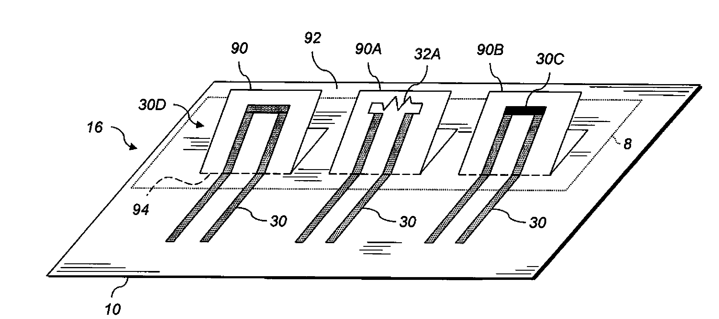
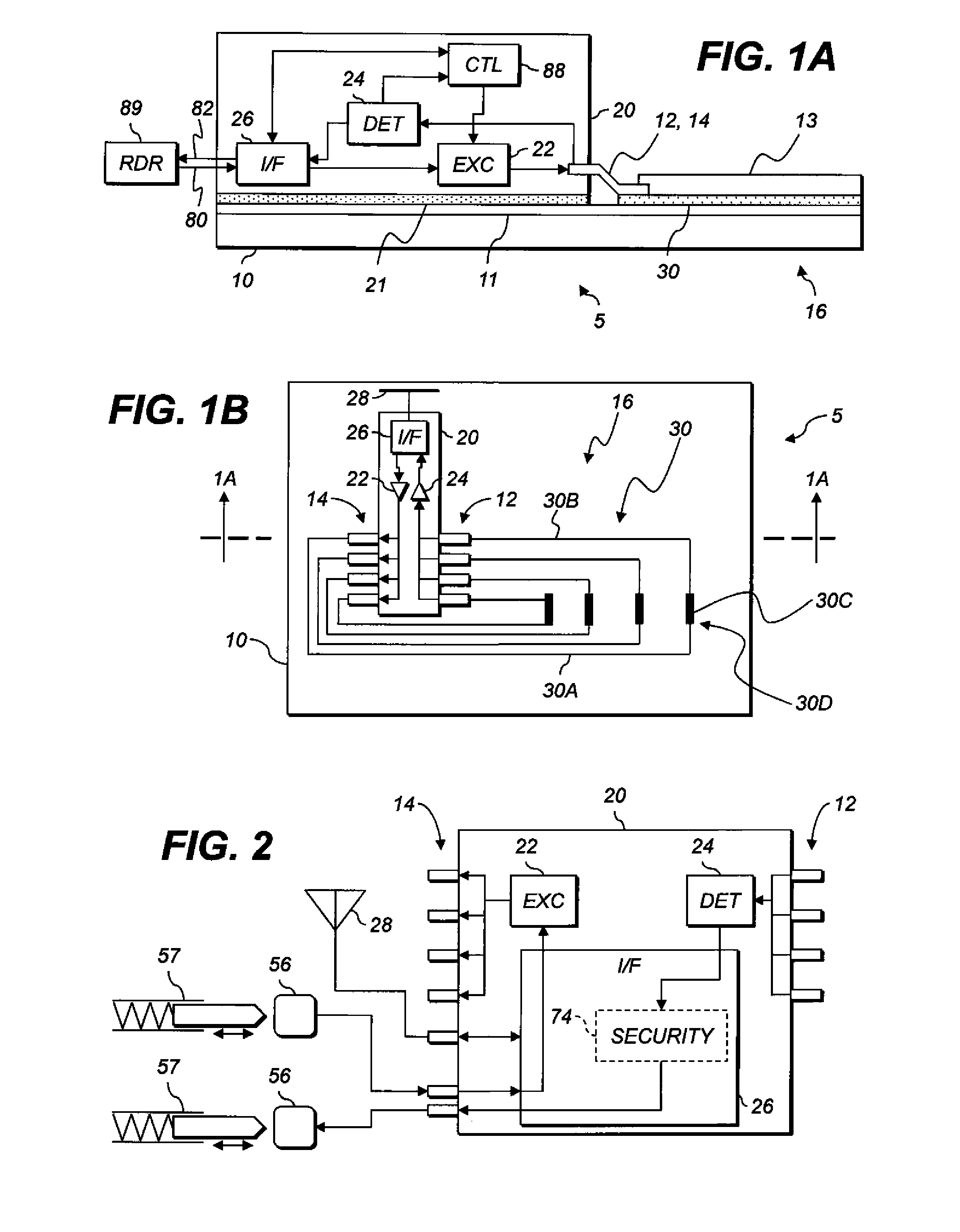
[0048]In the following description, some embodiments will be described in terms that would ordinarily be implemented as software programs. Those skilled in the art will readily recognize that the equivalent of such software can also be constructed in hardware. Because communications algorithms and systems are well known, the present description will be directed in particular to algorithms and systems forming part of, or cooperating more directly with, systems and methods described herein. Other aspects of such algorithms and systems, and hardware or software for producing and otherwise processing the data involved therewith, not specifically shown or described herein, are selected from such systems, algorithms, components, and elements known in the art. Given the systems and methods as described herein, software not specifically shown, suggested, or described herein that is useful for implementation of any embodiment is conventional and within the ordinary skill in such arts.

[0049]F...


PUM


Abstract

A method of altering an electronic storage system includes receiving the system including a substrate with an alteration region. The system also includes a code circuit disposed over the substrate and a transceiver. The code circuit includes a conductor disposed over the substrate at least partly in the alteration region, the conductor having a mechanical state and being adapted to permit external alteration of the mechanical state. The transceiver detects an electrical state corresponding to the mechanical state of the conductor, and, in response to a downlink signal, transmits an uplink signal representing the electrical state. After the system is received, the mechanical state of the conductor in the alteration region is altered.

Description

CROSS REFERENCE TO RELATED APPLICATIONS[0001]Reference is made to commonly assigned U.S. application Ser. No. (Attorney Docket No. K000286), filed concurrently herewith, titled “ELECTRONIC STORAGE SYSTEM WITH CODE CIRCUIT;” U.S. application Ser. No. (Attorney Docket No. K000972), filed concurrently herewith, titled “MAKING ELECTRONIC STORAGE SYSTEM HAVING CODE CIRCUIT;” U.S. application Ser. No. (Attorney Docket No. K000909), filed concurrently herewith, titled “ELECTRONIC STORAGE SYSTEM WITH EXTERNALLY-ALTERABLE CONDUCTOR;” U.S. application Ser. No. (Attorney Docket No. K000910), filed concurrently herewith, titled “ELECTRONIC STORAGE SYSTEM WITH ENVIRONMENTALLY-ALTERABLE CONDUCTOR;” U.S. application Ser. No. (Attorney Docket No. K001001), filed concurrently herewith, titled “MAKING STORAGE SYSTEM HAVING ENVIRONMENTALLY-MODIFIABLE CONDUCTOR;” and U.S. application Ser. No. (Attorney Docket No. K001002), filed concurrently herewith, titled “MAKING STORAGE SYSTEM HAVING MODIFIABLE CON...

Claims


Application Information

Patent Timeline
Patent Type & Authority Applications(United States)
IPC IPC(8): G06K1/00G06K1/02G06K1/12
CPCG06K19/067G06K1/12G06K19/07798
Inventor COK, RONALD STEVENLYONS, CHRISTOPHER
Owner EASTMAN KODAK CO
Learn More