
Radio frequency identification rivet

a technology of radio frequency identification and rivets, applied in the direction of identification means, instruments, computing, etc., can solve the problems of all conventional radio frequency identification systems working problematically, poor identification always happens,

Inactive Publication Date: 2013-10-31
HUANG PO WEI
View PDF1 Cites 9 Cited by
  • Summary
  • Abstract
  • Description
  • Claims
  • Application Information

AI Technical Summary

Benefits of technology

This patent is for a special type of bolt that can be used to attach things to each other, like metallic objects, containers, clothing, and bags. The bolt has certain features that make it hard to remove or counterfeit. The purpose of this invention is to provide a way to prevent theft and authenticate objects.

Problems solved by technology

However, for costly bottled products such as drugs, chemical compounds or raw materials, more necessarily, they have to be prevented from being stolen in addition to worrying about if the cap is opened or not.
Moreover, when a conventional counterfeit cap is opened, the third antenna always cannot be torn off the second antenna, unable to promptly interrupt radio frequency identification signals to carry out anti-counterfeit effect.
And if the cap is made of metals or what is contained in the bottle is a liquid, they may interfere with signals to be accepted by the antenna of the radio frequency identification system; or if the radio frequency identification system is attached on the cap, a poor identification always happens.
Moreover, all of conventional radio frequency identification systems may work problematically if combined with flexible objects (such as a dropping bottle or a dropping bag).

Method used


Image

  • Radio frequency identification rivet
  • Radio frequency identification rivet
  • Radio frequency identification rivet

Examples


Embodiment Construction

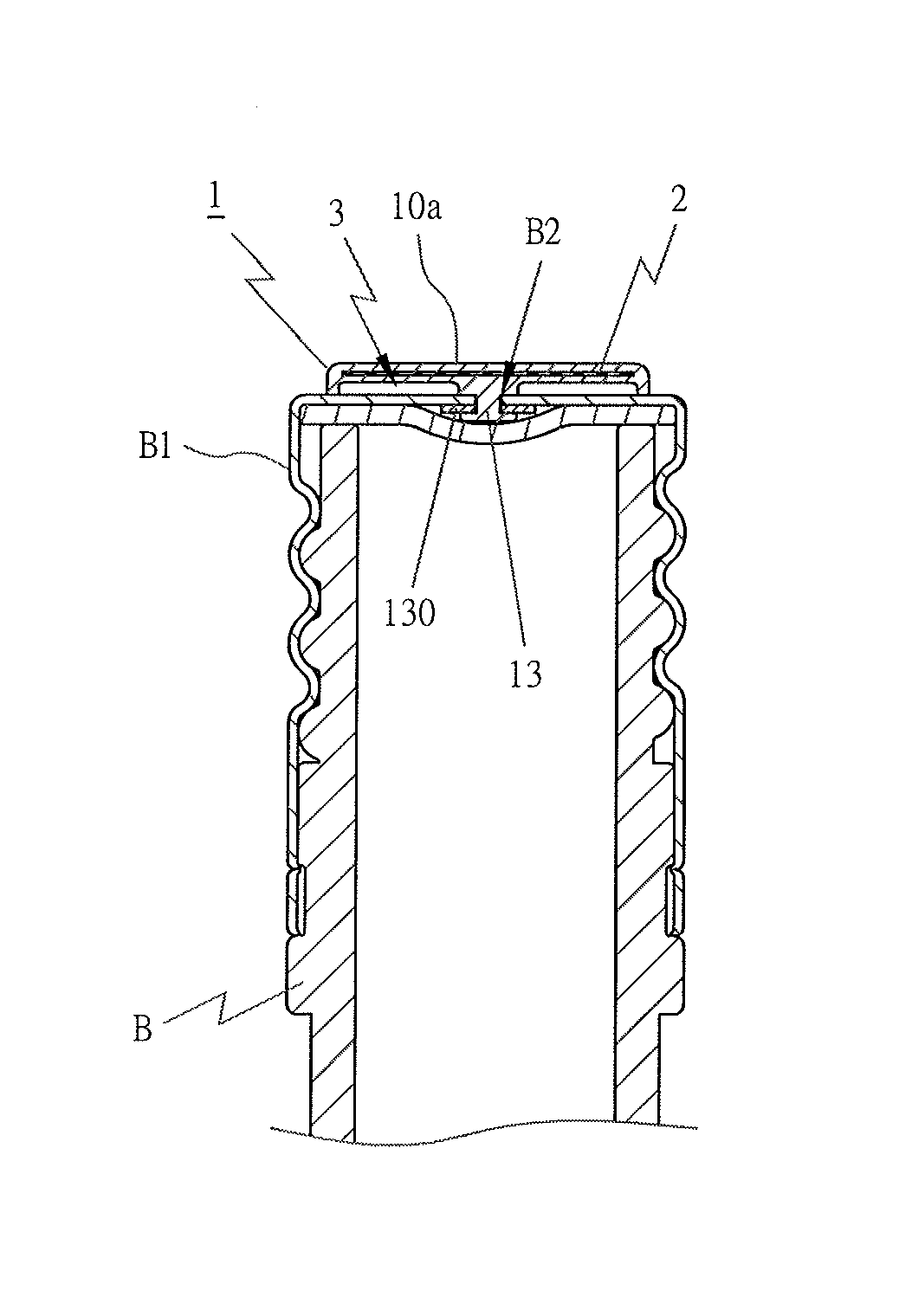
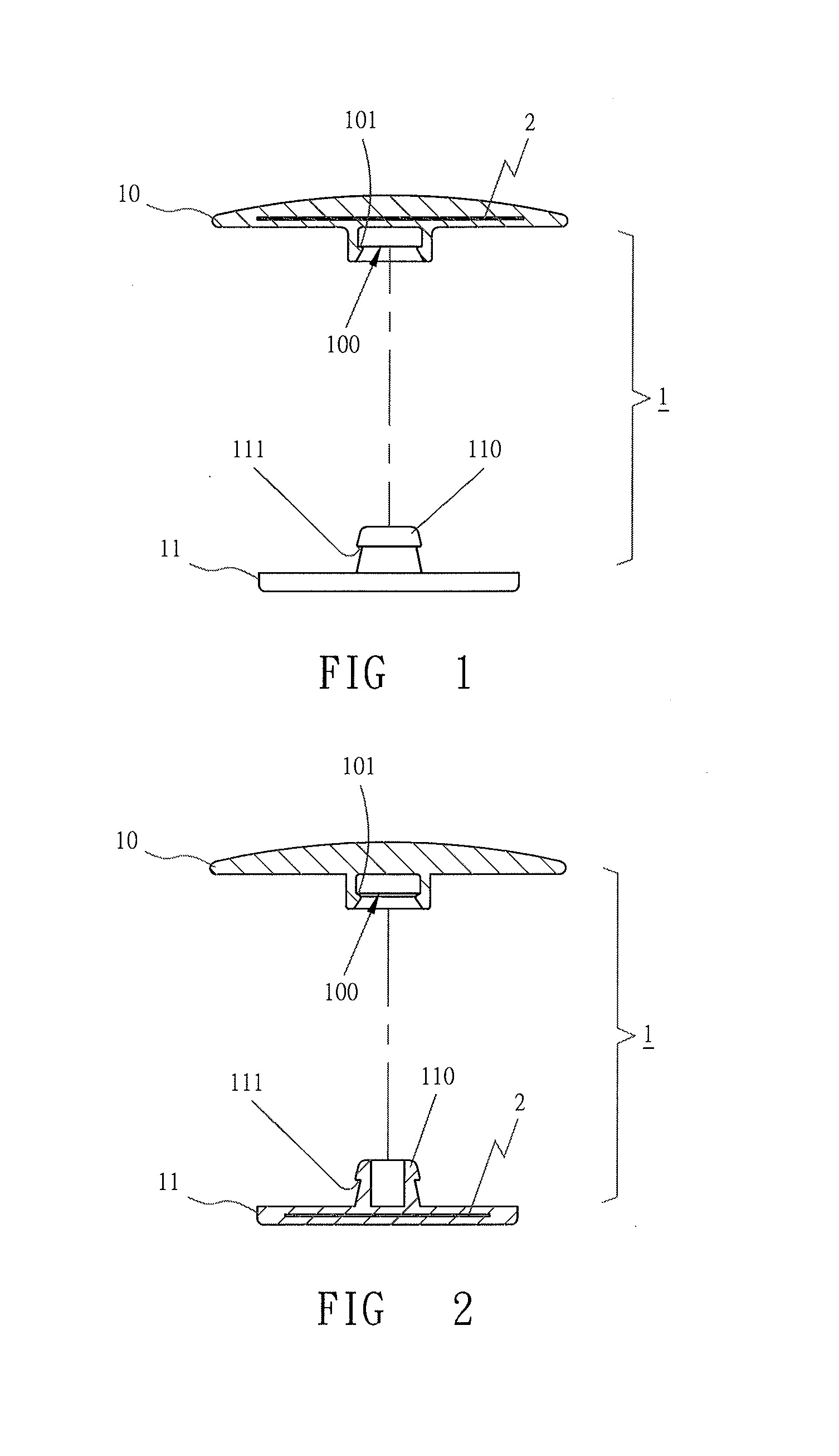
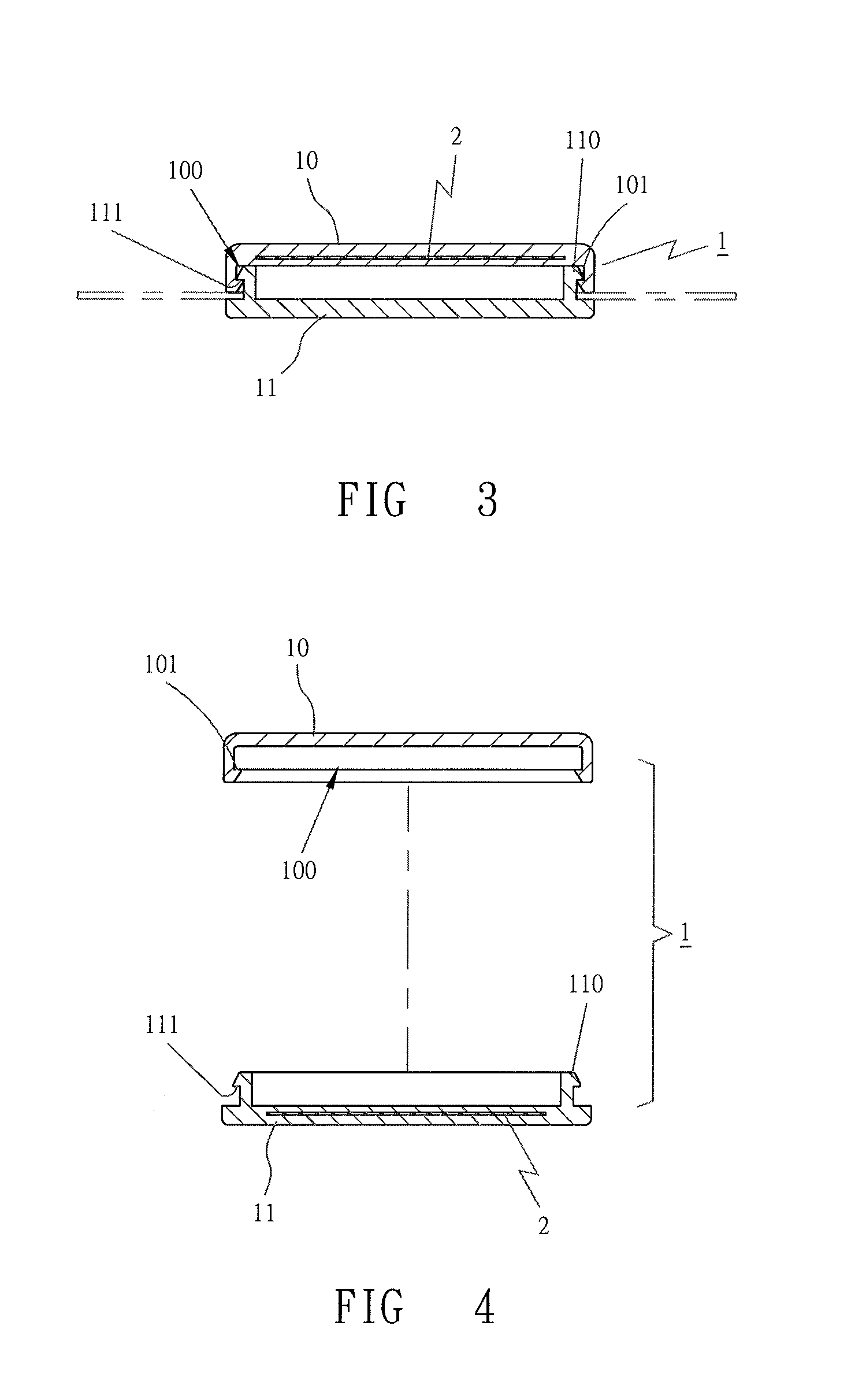
[0035]FIGS. 1-4 respectively show first four preferred embodiments of a radio frequency identification rivet in the present invention, mainly including a rivet 1 and a radio frequency identification system 2.

[0036]The rivet 1 is provided with two corresponding interlocking devices 10 and 11. The radio frequency identification system 2 is installed in the interlocking device 10 or 11, completely wrapped up while the interlocking device 10 or 11 is molded to prevent it from being damaged intentionally or unintentionally.

[0037]As shown in FIGS. 1-4, the interlocking devices 10 and 11 are combined together through diverse ways. The interlocking device 10 is bored with a joint groove 100 having an intermediate circumference shrunk inwards to form as an interlocking circumference 101. The interlocking device 11 possesses a joint base 110 having a front portion conically enlarged to form as an interlocking cone 111. As the joint base 110 of the interlocking device 11 is inserted in the joi...


PUM


Abstract

A radio frequency identification rivet at least includes a rivet consisting of two or more interlocking devices, or a single locking device, with a radio frequency identification system installed in the rivet. So any object jointed with the rivet can not only be identified with radio frequency, but also attain anti-theft and anti-counterfeit purposes, unless the rivet is forcefully damaged taken off the object.

Description

BACKGROUND OF THE INVENTION[0001]1. Field of the Invention[0002]This invention relates to a radio frequency identification rivet, particularly to one able to be jointed with objects to work with anti-theft and anti-counterfeit functions.[0003]2. Description of the Prior Art[0004]As disclosed in Taiwan Patent No. M355918 (Anti-Counterfeit Cap), it is to identify if the anti-counterfeit cap is opened or not, taking advantage of a third antenna to electrically connect with a first or a second antenna to tell if data stored in the radio frequency identification tag can be read. However, for costly bottled products such as drugs, chemical compounds or raw materials, more necessarily, they have to be prevented from being stolen in addition to worrying about if the cap is opened or not. And in order to break down induction of the radio frequency identification system, a thief may use tools or thermo measures (such as a microwave oven for trial in a supermarket) to destroy the radio frequen...

Claims


Application Information

Patent Timeline
Patent Type & Authority Applications(United States)
IPC IPC(8): G06K19/067
CPCG06K19/027G06K19/04G09F3/0335G08B13/2434G09F3/0323G06K19/07798
Inventor HUANG, PO-WEI
Owner HUANG PO WEI
Learn More