
LCD Device and Backlight Module

a backlight module and lcd technology, applied in the field of liquid crystal display, can solve the problems of affecting the planeness of the lcd panel to some extent, affecting the quality of the whole lcd device, and easy generation of excessive local stress on the lcd panel, so as to prevent excessive local stress

Inactive Publication Date: 2013-10-31
TCL CHINA STAR OPTOELECTRONICS TECH CO LTD
View PDF1 Cites 10 Cited by
  • Summary
  • Abstract
  • Description
  • Claims
  • Application Information

AI Technical Summary

Benefits of technology

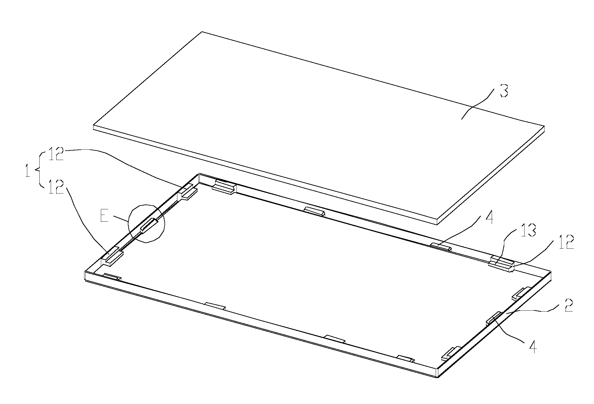
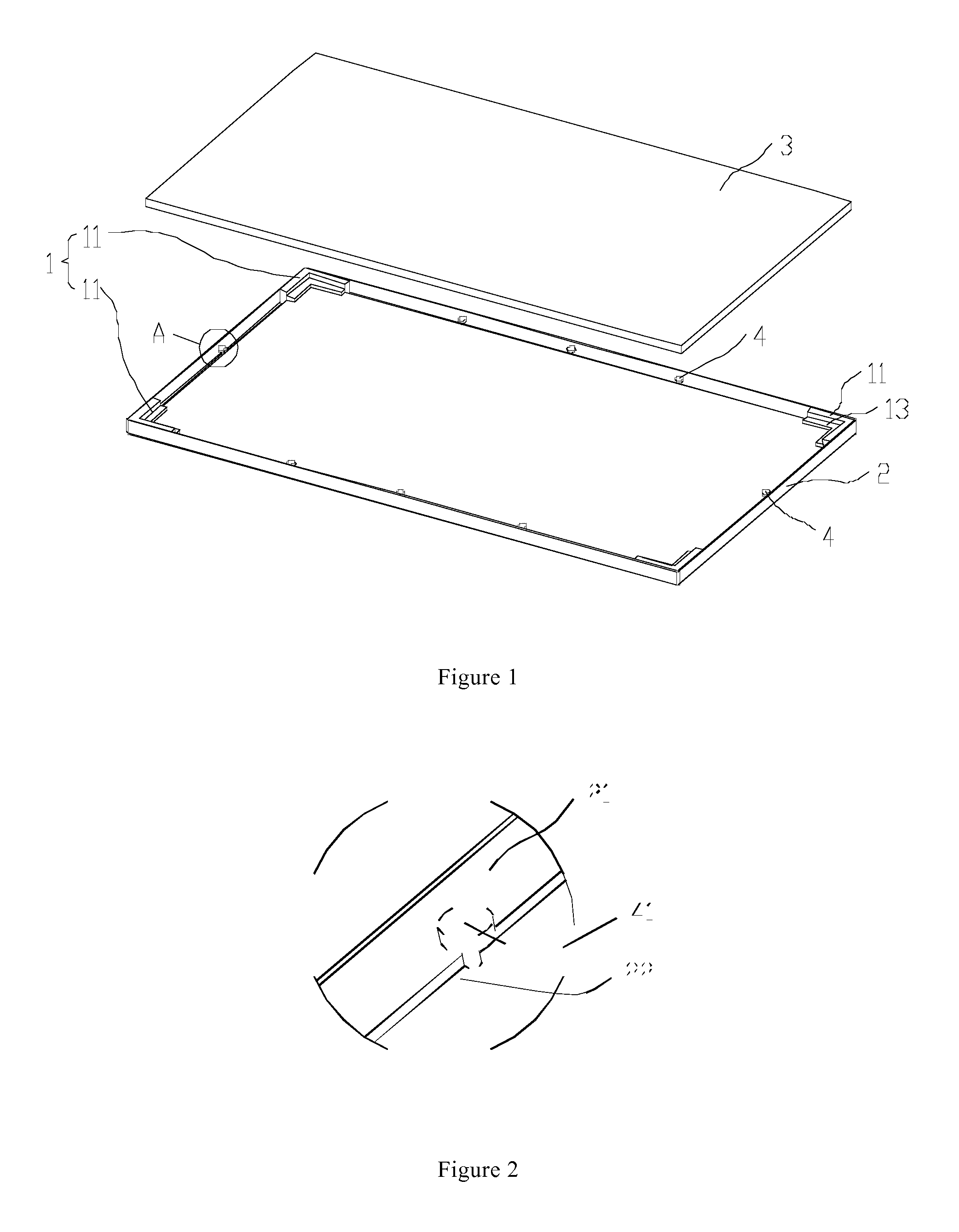
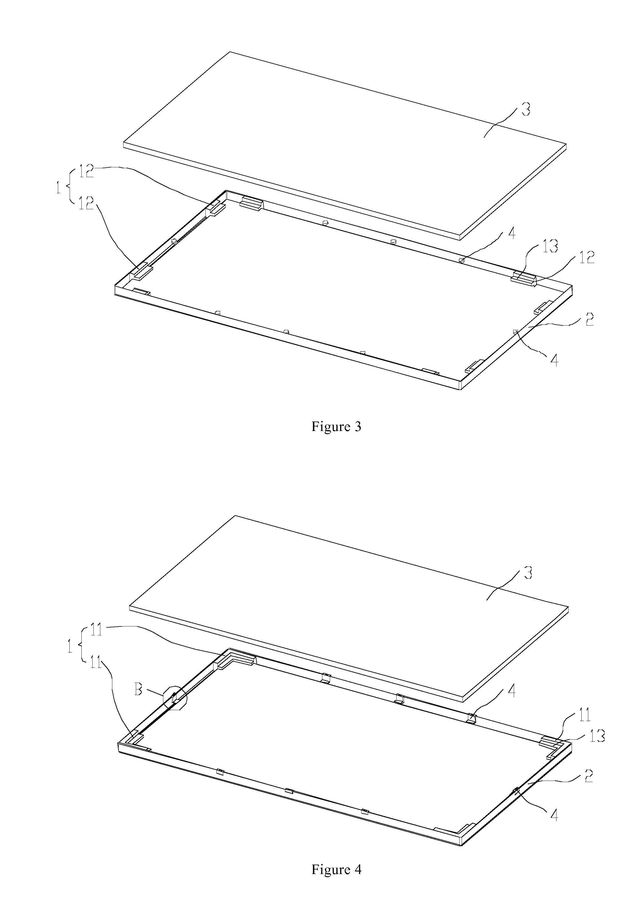
The technical effect of this patent is to provide an LCD device and backlight module with a segmented middle frame and low cost that ensure uniform support force on the LCD panel, avoid excessive local stress, and prevent blocking out the light emitted by the backlight module. This is achieved by additionally arranging support members on the LCD device and between adjacent member units, with the support surface of the support members flush with that of the middle frame to provide intermediate support force.

Problems solved by technology

When the distance between two adjacent member units of the LCD device is long, the planeness of the LCD panel is affected to some extent, and excessive local stress is easily generated on the LCD panel.
The LCD panel includes thin glass substrate(s) which is hard and fragile, and the glass substrate is easily damaged because of stress concentration, resulting in adverse effect on the quality of the whole LCD device.

Method used


Image

  • LCD Device and Backlight Module
  • LCD Device and Backlight Module
  • LCD Device and Backlight Module

Examples


Embodiment Construction

[0039]The invention provides an LCD device, comprising a backlight module; the backlight module comprises a middle frame 1, and a backplane 2. As shown in FIG. 1 and FIG. 2, the LCD device of a first example comprises a middle frame 1, a backplane 2, and an LCD panel 3; the LCD panel 3 is arranged on a support surface 13 of the middle frame 1; the middle frame 1 comprises a plurality of member units, and a distance is reserved between two adjacent member units. The backlight module further comprises a support member(s) 4 used for assistantly supporting the LCD panel 3; the support member(s) 4 is fixedly arranged on the backplane 2, and the support member 4 is positioned between two adjacent member units; a support surface 41 of the support member 4 is flush with the support surface 13 of the middle frame 1.

[0040]The support member(s) 4 of the LCD panel is additionally arranged on the LCD device of the invention, and the support member(s) 4 is arranged between two member units when t...


PUM

PropertyMeasurementUnit
distanceaaaaaaaaaa
widthaaaaaaaaaa
sizesaaaaaaaaaa

Abstract

The invention relates to the field of LCDs, and more particularly to an LCD device and a backlight module. The LCD device includes a middle frame, a backplane, and an LCD panel; the LCD panel is arranged on a support surface of the middle frame; the middle frame includes a plurality of member units, and a distance is reserved between two adjacent member units. The LCD device further comprises a support member(s) used for assistantly supporting the LCD panel; the support member(s) is fixedly arranged on the backplane, and the support member is positioned between adjacent member units; the support surface of the support member is flush with the support surface of the middle frame. The support member(s) of the LCD panel is additionally arranged on the LCD device of the invention; the support member(s) is arranged between two member units when the distance between two adjacent member units is long to provide intermediate support force, so as to enable the support force obtained by the LCD panel is more uniform, and prevent excessive local stress.

Description

TECHNICAL FIELD[0001]The invention relates to the field of liquid crystal displays (LCDs), and more particularly to an LCD device and a backlight module.BACKGROUND[0002]A conventional LCD device generally includes a front frame, an LCD panel, a middle frame, a backlight module, a back cover and the like. The backlight module includes an optical film, a light guide panel (LGP), a lightbar and the like. The front frame, the middle frame and the back cover respectively have different functions; the front frame is mainly used for fixing the LCD panel and preventing the LCD panel from escaping, the middle frame is mainly used for bearing the LCD panel and shielding partial backlight module from light leakage, and the back cover is mainly used for bearing the optical film, the LGP, the lightbar and the like and ensuring the planeness of the backlight module.[0003]To save cost, a part of LCD devices employ a segmented middle frame. The middle frame includes a plurality of member units; the...

Claims


Application Information

Patent Timeline
Patent Type & Authority Applications(United States)
IPC IPC(8): G02F1/13357
CPCG02F1/133308G02F1/133608G02F1/133317
Inventor KUO, YICHENGCHEN, SHIHHSIANGYU, GANGZHOU, GEGEWANG, JIAQIANG
Owner TCL CHINA STAR OPTOELECTRONICS TECH CO LTD
Learn More