Indirect linear fixture

a linear fixture and indirect technology, applied in the field of indirect lighting troffers, can solve the problems of very energy-inefficient incandescent lights, relatively inefficient leds, and significantly longer operational life of leds

Active Publication Date: 2013-10-31
IDEAL IND LIGHTING LLC
View PDF7 Cites 33 Cited by
  • Summary
  • Abstract
  • Description
  • Claims
  • Application Information

AI Technical Summary

Benefits of technology

[0018]Another embodiment of a fixture has a housing shaped to define two or more interior surfaces, with a back reflector on each of the interior surfaces. The fixture has a heat sink proxima...

Problems solved by technology

Incandescent lights are very energy-inefficient light sources with approximately ninety percent of the electricity they consume being released as heat rather than light.
Fluorescent light bulbs are more energy efficient than incandescent light bulbs by a factor of about 10, but are still relatively inefficient.
In addition, LEDs can have a significantly longer operational lifetime.
Incandescent light bulbs have relatively short lifetimes, with some having a lifetime in the range of about 750-1000 hours.
Fluorescent bulbs can also have lifetimes longer than incandescent bulbs such as in the range of approximately 10,000-20,000 hours, but provide less desirable color reproduction.
Because of the physical arrangement of the various source elements, multicolor sources often cast shadows with color separation and provide an output with poor color uniformity.
Thus, one challenge associated with multicolor light sources is good spatial c...

Method used


Image

  • Indirect linear fixture
  • Indirect linear fixture
  • Indirect linear fixture

Examples


Embodiment Construction

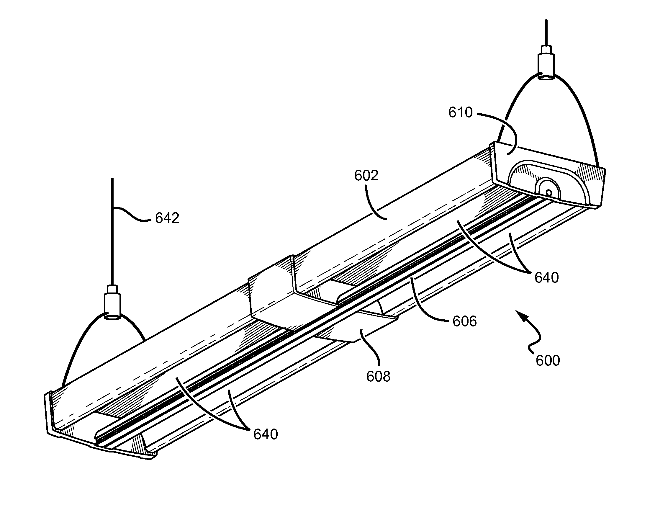
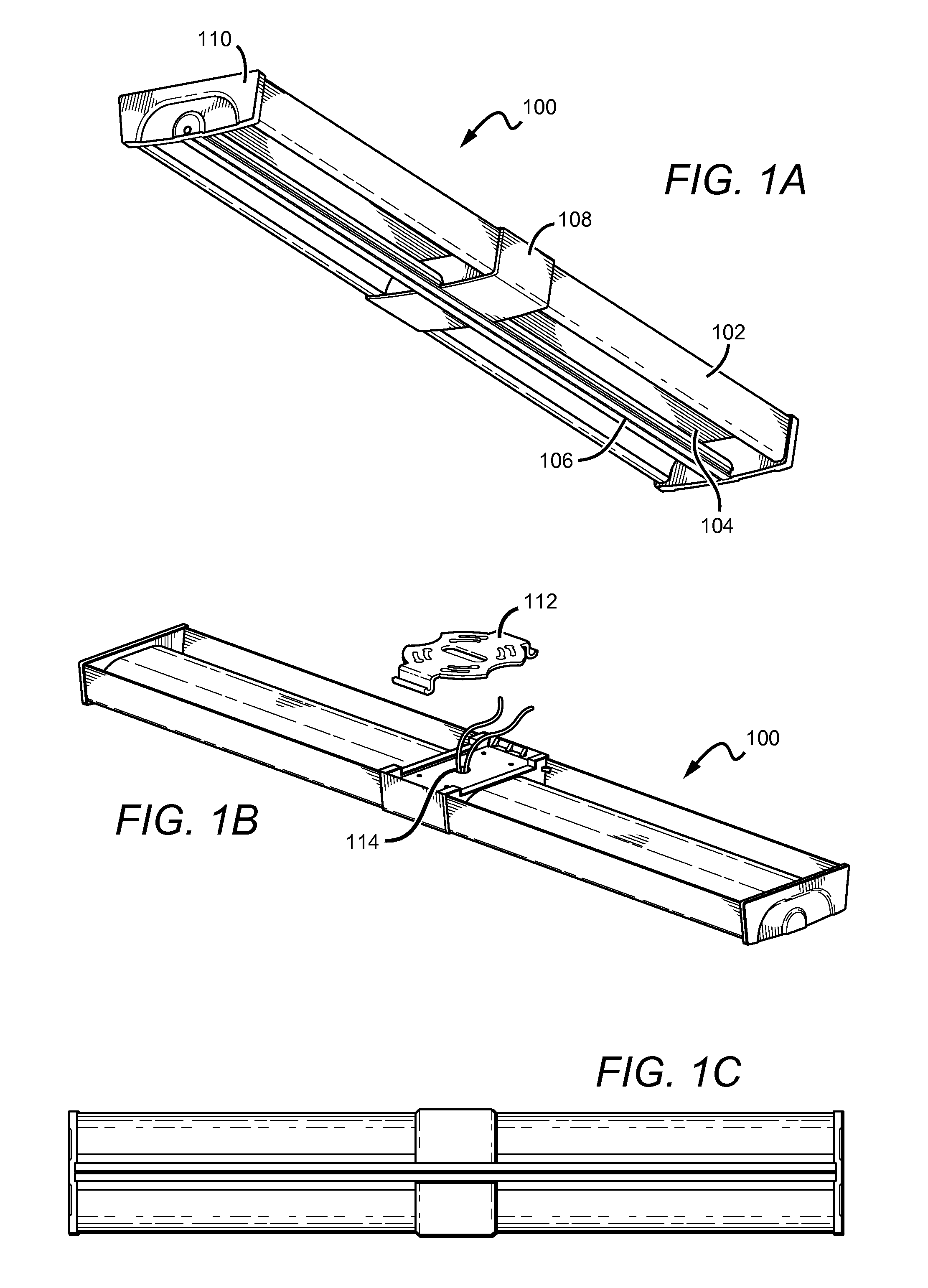
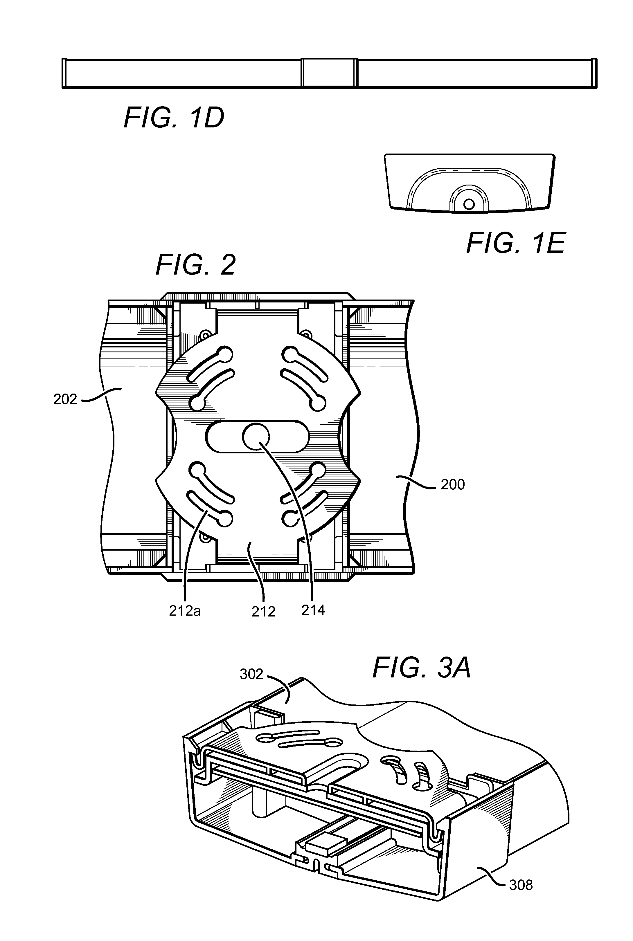
[0034]Embodiments of the present invention provide a troffer-style fixture that is particularly well-suited for use with solid state light sources, such as LEDs. The troffer comprises a light engine unit that is surrounded on its perimeter by a reflective pan. A back reflector defines a reflective surface of the light engine. To facilitate the dissipation of unwanted thermal energy away from the light sources, a heat sink is disposed proximate to the back reflector. In some embodiments, one or more lens plates extend from the heat sink out to the back reflector. A portion of the heat sink is exposed to the ambient environment outside of the cavity. The portion of the heat sink inside the facing the back reflector functions as a mount surface for the light sources, creating an efficient thermal path from the sources to the ambient. One or more light sources disposed along the heat sink mount surface emit light into the interior where it can be mixed and / or shaped before it is emitted...


PUM


Abstract

A light fixture comprising a chamber portion is disclosed. In some embodiments, the fixture comprises a chamber portion shaped to house circuitry required for lighting elements such as light emitting diodes (LEDs) mounted elsewhere in the fixture. In some embodiments, LEDs are mounted facing a back reflector, which in turn reflects light out of a troffer to form an indirect lighting fixture. In some embodiments, light is emitted from one mixing chamber. In some embodiments, light is emitted from two or more mixing chambers. In some embodiments, LEDs are mounted on a heat sink which cooperates with a chamber portion.

Description

RELATED APPLICATION[0001]This application claims the benefit of U.S. Provisional Application No. 61 / 622,482, filed on 10 Apr. 2012, and also claims the benefit of U.S. Provisional Application No. 61 / 705,585, filed on 25 Sep. 2012, both of which are incorporated by reference herein in their entirety.BACKGROUND OF THE INVENTION[0002]1. Field of the Invention[0003]The invention relates to lighting troffers and, more particularly, to indirect lighting troffers that are well-suited for use with solid state lighting sources, such as light emitting diodes (LEDs).[0004]2. Description of the Related Art[0005]Troffer-style fixtures are ubiquitous in commercial office and industrial spaces throughout the world. In many instances these troffers house elongated fluorescent light bulbs that span the length of the troffer. Troffers may be mounted to or suspended from ceilings. Often the troffer may be recessed into the ceiling, with the back side of the troffer protruding into the plenum area abov...

Claims


Application Information

Patent Timeline
IPC IPC(8): F21K99/00F21S8/02F21S8/04
CPCF21K9/17F21S8/026F21S8/04F21S8/06F21V7/0008F21V21/02F21V23/009F21V25/12F21V29/70F21Y2103/10F21Y2115/10
Inventor LAY, MICHAELSNELL, NATHAN
Owner IDEAL IND LIGHTING LLC
Why Eureka
Try Eureka