Direct connection between a tube and a flat element

a flat element and connection technology, applied in the direction of bracing pipes, pipes, fastening means, etc., can solve the problems of significant time and installation costs

Active Publication Date: 2013-10-31
EURO DE CONSTR METALICAS
View PDF22 Cites 0 Cited by
  • Summary
  • Abstract
  • Description
  • Claims
  • Application Information

AI Technical Summary

Benefits of technology

[0014]The screws, rivets, etc. work in double shear, increasing with it the resistance capacity of the joining.
[0015]Since it is an open-type configuration, it allows the internal galvanization of the tube.
[0016]In order to complete the description below and with the purpose of aiding a better comprehension of the direct connection between a tube and a flat element, a set of plans which figures represent the most significant details of the invention in an illustrative rather than limitative manner is attached to the present specification.

Problems solved by technology

In the current state of the art, the joining of the tubes to the nodes is carried out by means of direct welding or by means of the installation of terminal elements at the ends of the tubes, allowing the connection to the nodes by means of welding or any other time of equivalent attachment, which supposes significant time and installation costs.
However, the type of connector used is only valid for circular bars, its shape also supposing a weak spot at the ends of the bars.

Method used


Image

  • Direct connection between a tube and a flat element
  • Direct connection between a tube and a flat element
  • Direct connection between a tube and a flat element

Examples


Embodiment Construction

[0006]The direct connection between a tube and a flat element object of the present registry solves the aforementioned inconveniences and also contributes additional advantages that will be evident based on the description below.

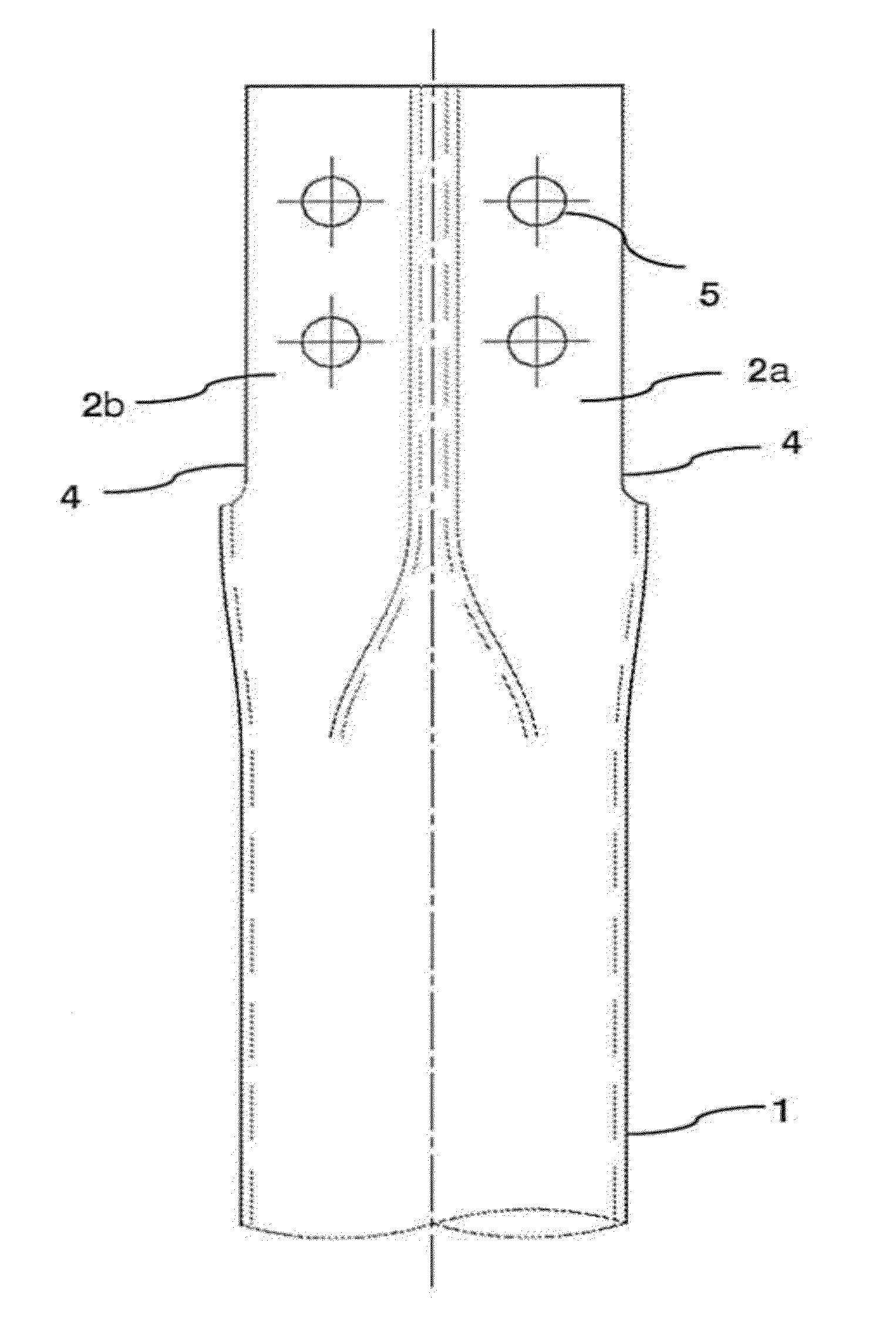
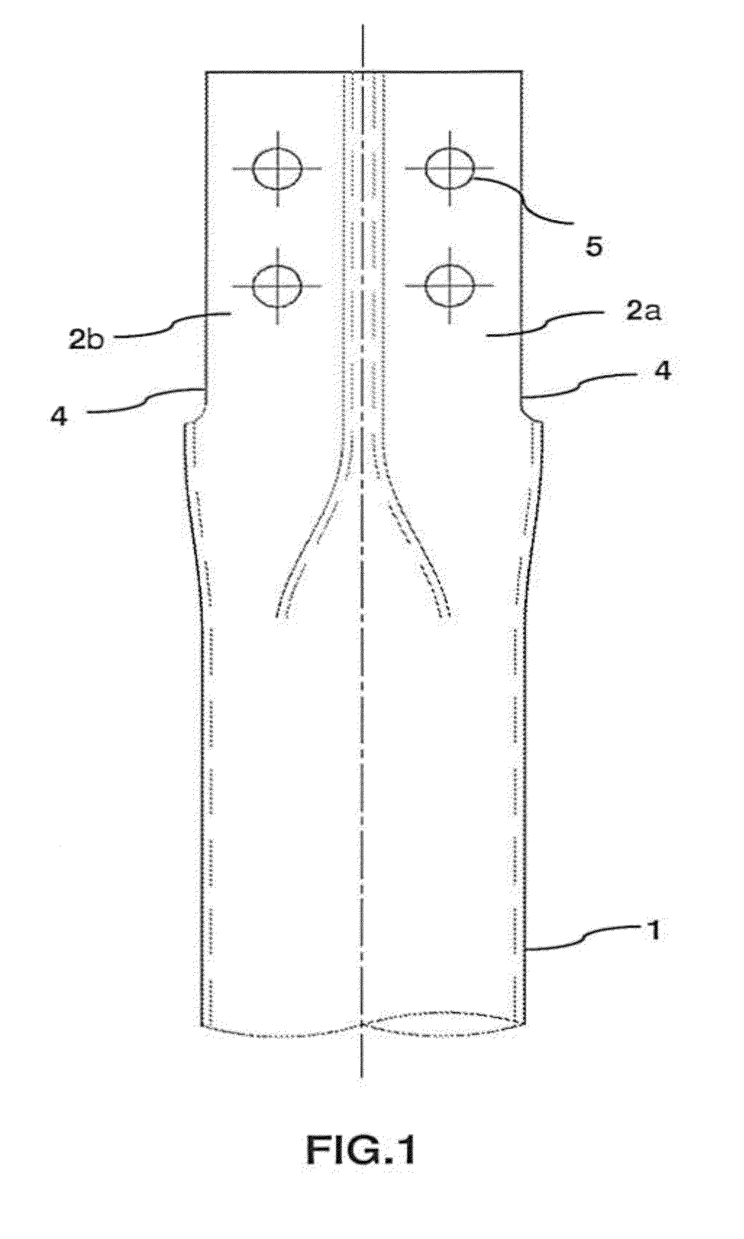
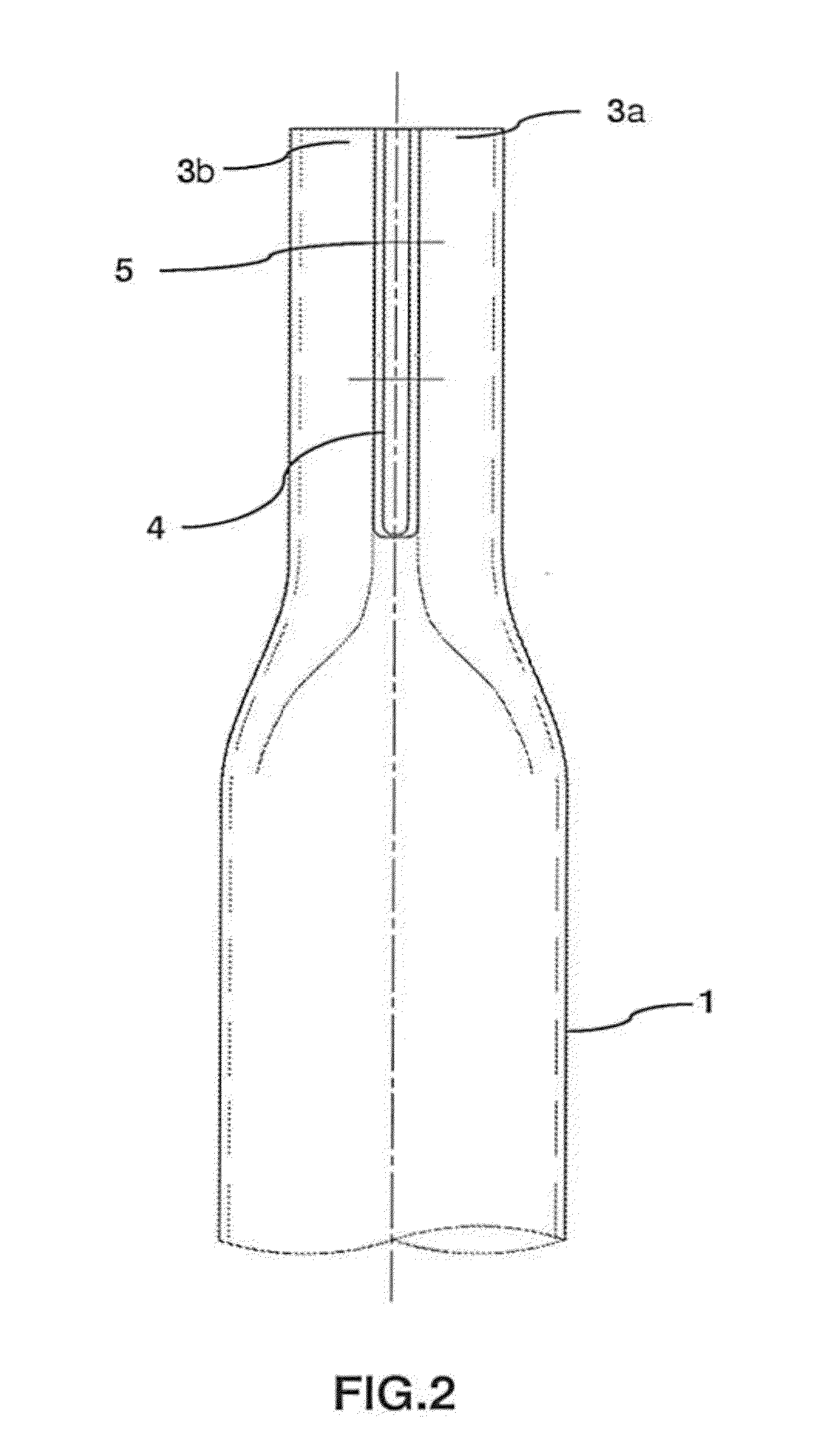
[0007]The invention is based on the formation of a connector through the deformation, preferably by stamping, of the end or ends of a tube, thus configuring two star-shaped joining elements having two planes, preferably perpendicular, in such a way that slots are made at the ends of one of the planes for the correct reception of the flat element, until it is positioned inside the end of the tube.

[0008]In this same plane and perpendicularly thereof, as many drill holes are necessary are made for the attachment of the end of the tube to the flat element, this attachment being made by means of screws, rivets or other elements. Optionally, if the attachment procedure is made by welding, said drill holes would not be necessary.

[0009]Likewise and owing to the defo...


PUM


Abstract

The invention relates to a direct connection between a tube and a flat element by means of a connector preferably formed by stamping on the tube itself, which enables joining the latter to the flat element, without auxiliary elements, by nest-like insertion of same into the flat element and subsequent attachment by means of screws, rivets, bolts, pins or other elements. Said connection can be used in the construction of modular two-dimensional or three-dimensional tubular structures forming a single, double, or multi-layer latticework, preferably for supporting parabolic trough solar collectors.

Description

OBJECT OF THE INVENTION[0001]Direct connection between a tube and a flat element.BACKGROUND OF THE INVENTION[0002]The present invention relates to a direct connection between a tube and a flat element, direct connection being understood as that connection which does not need auxiliary elements such as couplings, flanges, clamps, etc.[0003]In general, the main function of the solution is the direct connection between a circular or square tube and a flat element such as a plate, sheet, gusset, etc.[0004]Likewise, the invention is especially applicable to the construction of modular two-dimensional or three-dimensional tubular structures. These types of structures are constituted by a simple, double or even multi-layered latticework of tubular bars that are joined at intervals at common points or nodes.[0005]The joining of two or three tubes is the simplest form of the connection node, however, nodes implying a larger number of tubes are quite common. In these cases, the tubular member...

Claims


Application Information

Patent Timeline
Patent Type & Authority Applications(United States)
IPC IPC(8): F16B17/00
CPCF16B17/006E04B1/19E04B2001/193Y10T403/349Y10T403/46E04B2001/1936
Inventor MUNOZ FERNANDEZ, EDUARDOCARRASCO GIMENA, MAXIMILIANOPARRA FERNANDEZ-MOTA, JOSE IGNACIOGARRIDO DELGADO, LUIS
Owner EURO DE CONSTR METALICAS
Why Eureka
Try Eureka