
Air purification device

a technology of air purification device and air filter, which is applied in the direction of magnetic separation, separation process, transportation and packaging, etc., can solve the problems of not achieving optimal operation of the engine of the vehicle and the filtration method, and achieving the characteristic of providing cleaner air, so as to achieve the effect of a conventional vehicle and relatively low production cos

Inactive Publication Date: 2014-12-18
MORO FRANCO EUSEBIO
View PDF0 Cites 5 Cited by
  • Summary
  • Abstract
  • Description
  • Claims
  • Application Information

AI Technical Summary

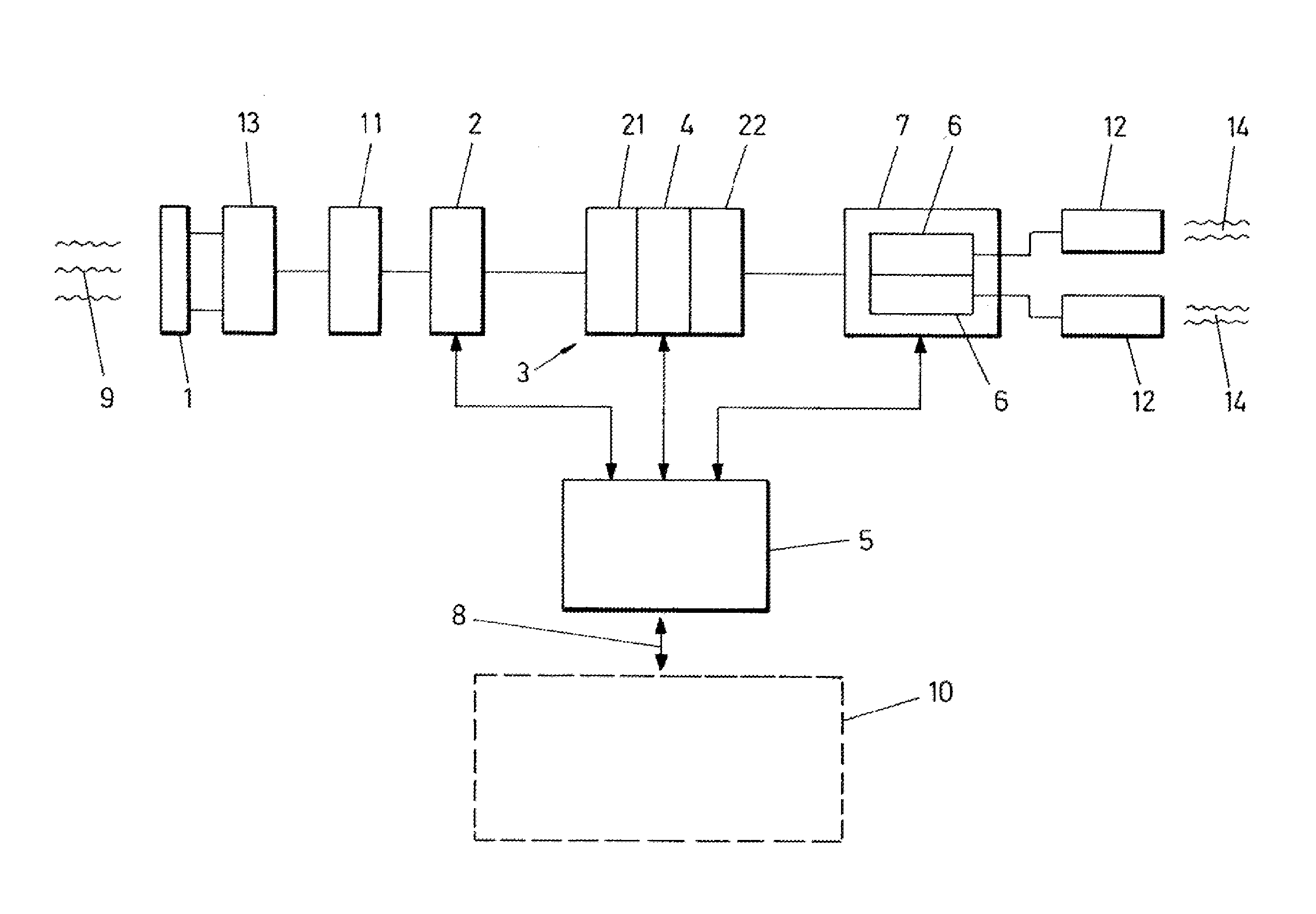
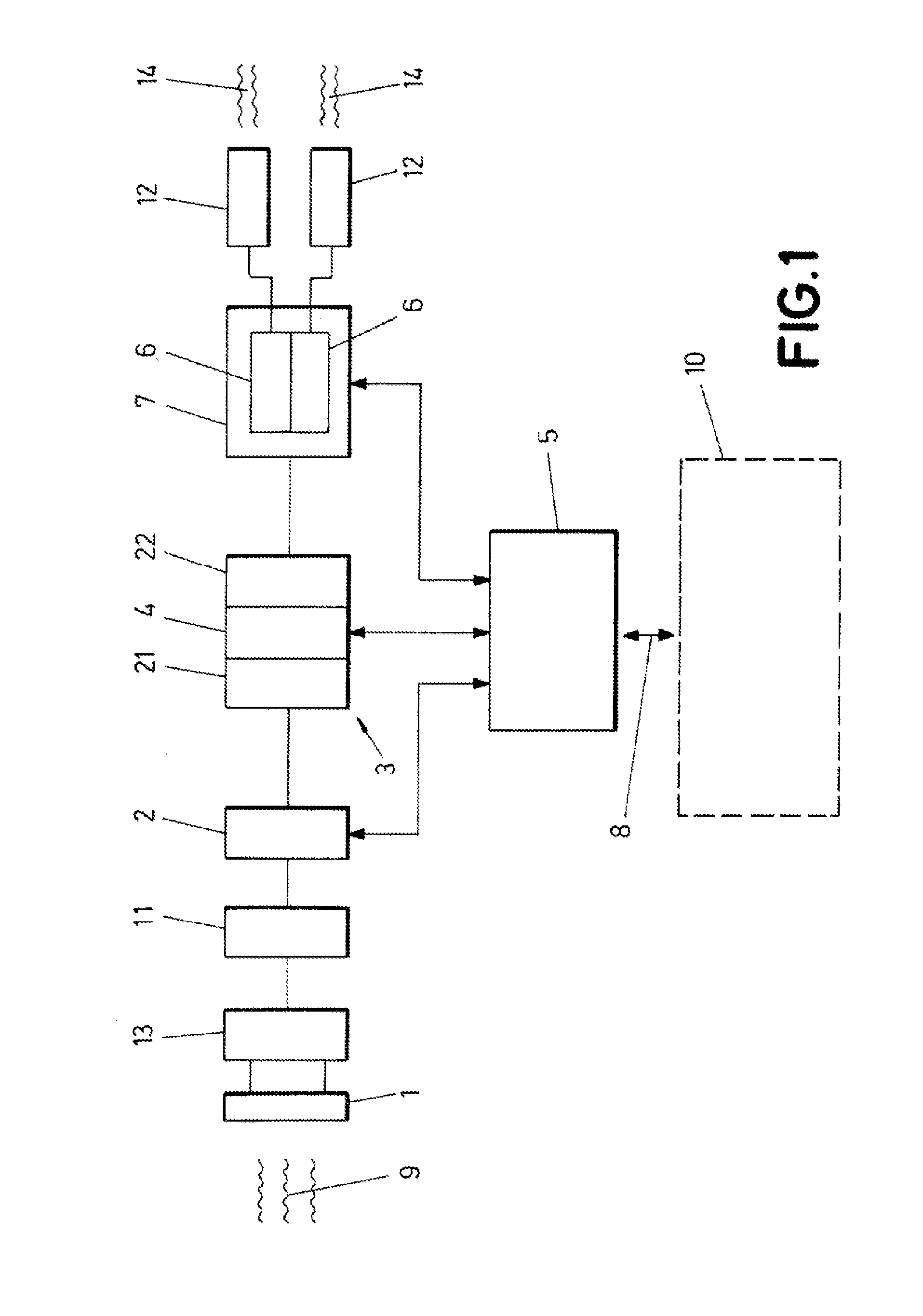
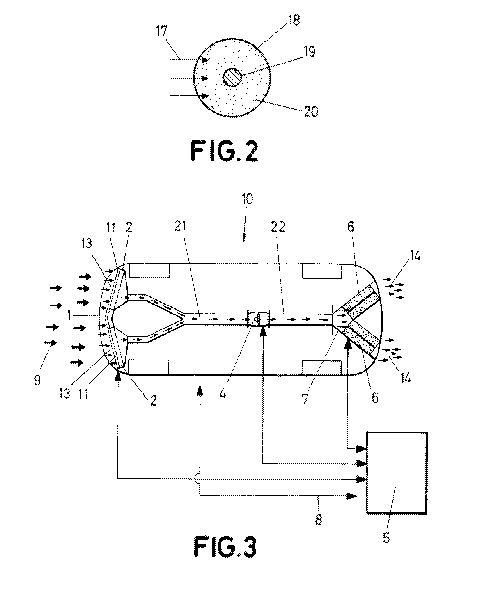
Benefits of technology

The invention is an air purification device that can be easily fitted to existing vehicles without the need for major modifications. It uses the vehicle's grille or air intake to filter out dirty air and directs the clean air outlet towards the exhausts. The device contains filters and a fan / aspirator, which are placed in the lower part of the vehicle. This makes it easy to install and can be used in different models of vehicles. The device can be activated using electrostatic filters and can be used in land, water, air, or space vehicles, and in mobile and stationary vehicles. The cost of production is relatively low compared to other air purification devices, as materials such as glass, metal alloys, and fans / aspirators are used. Overall, the invention provides a simple and effective solution to air pollution, making it a useful tool in the environmental cleaning agent.

Problems solved by technology

This document already intended to turn a vehicle into a mobile air purifier, there being inconveniences, advantages, and infeasibilities of different kinds that determined that its implementation in the engine of a vehicle and the filtration methodologies would not achieve an optimal operation.
Currently, there are many automobiles having multiple systems to capture and filter air, as well as the gases and pollution particles generated in their engines, but they lack the characteristic of providing cleaner air than the one they pick up to the environment, such that they become a more purifying rather than polluting element.

Method used


Image

  • Air purification device
  • Air purification device
  • Air purification device

Examples


Embodiment Construction

[0011]In order to achieve the objectives and avoid the inconveniences indicated in the previous sections, the invention consists of an air purification device that comprises at least one water, air, space, or land vehicle, and which includes at least air intakes and outlets; such that the intakes receive a flow of dirty air and the outlets provide at least one flow of clean air.

[0012]In a novel manner, according to the invention, the device thereof has air ducts in which a fan / aspirator is interposed, passive and mechanical air-filtration elements being placed before the unit formed by said ducts and fan / aspirator. At the exit from said unit there is an active filtration module that includes one or more non-thermal plasma conduits, such that when the ducts closest to the module bifurcate or branch inside said module, they define at least two clear air outlets, said unit, said module and a filter of said passive and mechanical filtration elements being connected to a control unit, an...


PUM


Abstract

The device has air ducts (21, 22) in which a fan / aspirator (4) is interposed, passive and mechanical air-filtration elements (2, 11, 13) being placed before the unit (3) formed. At the exit from said unit (3) there is an active filtration module that includes one or more non-thermal plasma conduits (6). When the ducts (22) closest to the module (7) bifurcate or branch inside said module (7), they define at least two clear air outlets (12), said unit (3), said module (7) and a filter (2) of said passive and mechanical filtration elements being connected to a control unit (5) by means of a communication (8) selected from mechanical, electrical, electronic and optoelectronic means and any combination thereof. The device can be used in land, water, air or space vehicles (10).

Description

OBJECT OF THE INVENTION[0001]The present invention, as expressed in the wording of this specification, relates to an air purification device which essential purpose is facilitating a small environmental air purification system applied to a land vehicle; however, its application to all kinds of stationary or mobile vehicles should not be ruled out, including water, land, air or space vehicles because, due to the configuration, architecture, and type of filters used, the device allows operations with very diverse flow rates, flows, and capacities of the airs being handled, using glass ball filters, electrostatic filtration elements and others, including HEPA filters and DBD reactors, to achieve the foregoing. With it, a vehicle, whether or not it has polluting characteristics in its propulsion or operation, may be turned into an element that delivers cleaner air than the air it picks up to the environment, the dirt particles remaining in the device itself, with which an important mean...

Claims


Application Information

Patent Timeline
IPC IPC(8): B03C3/36B01D50/00B01D53/04
CPCB03C3/366B03C2201/30B01D50/00B01D53/0407A61L9/16A61L9/22A61L2209/14B01D2279/40B60H3/0078B60H3/0641
Inventor MORO FRANCO, EUSEBIO
Owner MORO FRANCO EUSEBIO
Learn More