Co-forged golf club head and method of manufacture

a golf club head and co-forged technology, applied in the field of co-forged golf club heads, can solve the problems of not taking advantage of extreme forgiveness, affecting the feel and reducing the performance of the golf club head when compared to a direct center hi

a golf club head and co-forged technology, applied in the field of co-forged golf club heads, can solve the problems of not taking advantage of extreme forgiveness, affecting the feel and reducing the performance of the golf club head when compared to a direct center hi

US20130288823A1Inactive Publication Date: 2013-10-31ACUSHNET CO

Image

  • Co-forged golf club head and method of manufacture
  • Co-forged golf club head and method of manufacture
  • Co-forged golf club head and method of manufacture

Examples


Embodiment Construction

[0031]The following detailed description is of the best currently contemplated modes of carrying out the invention. The description is not to be taken in a limiting sense, but is made merely for the purpose of illustrating the general principles of the invention, since the scope of the invention is best defined by the appended claims.

[0032]Various inventive features are described below that can each be used independently of one another or in combination with other features. However, any single inventive feature may not address any or all of the problems discussed above or may only address one of the problems discussed above. Further, one or more of the problems discussed above may not be fully addressed by any of the features described below.

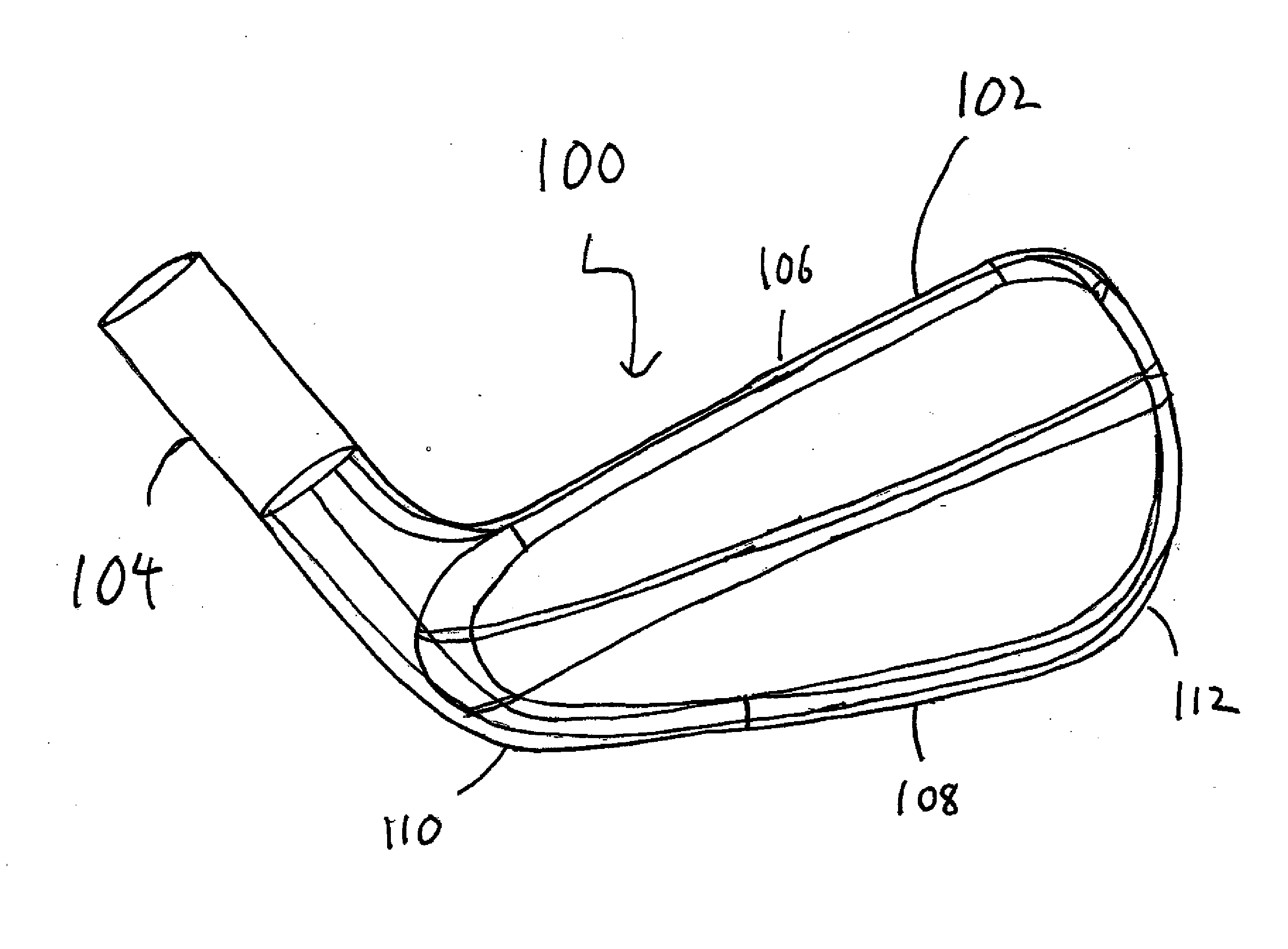
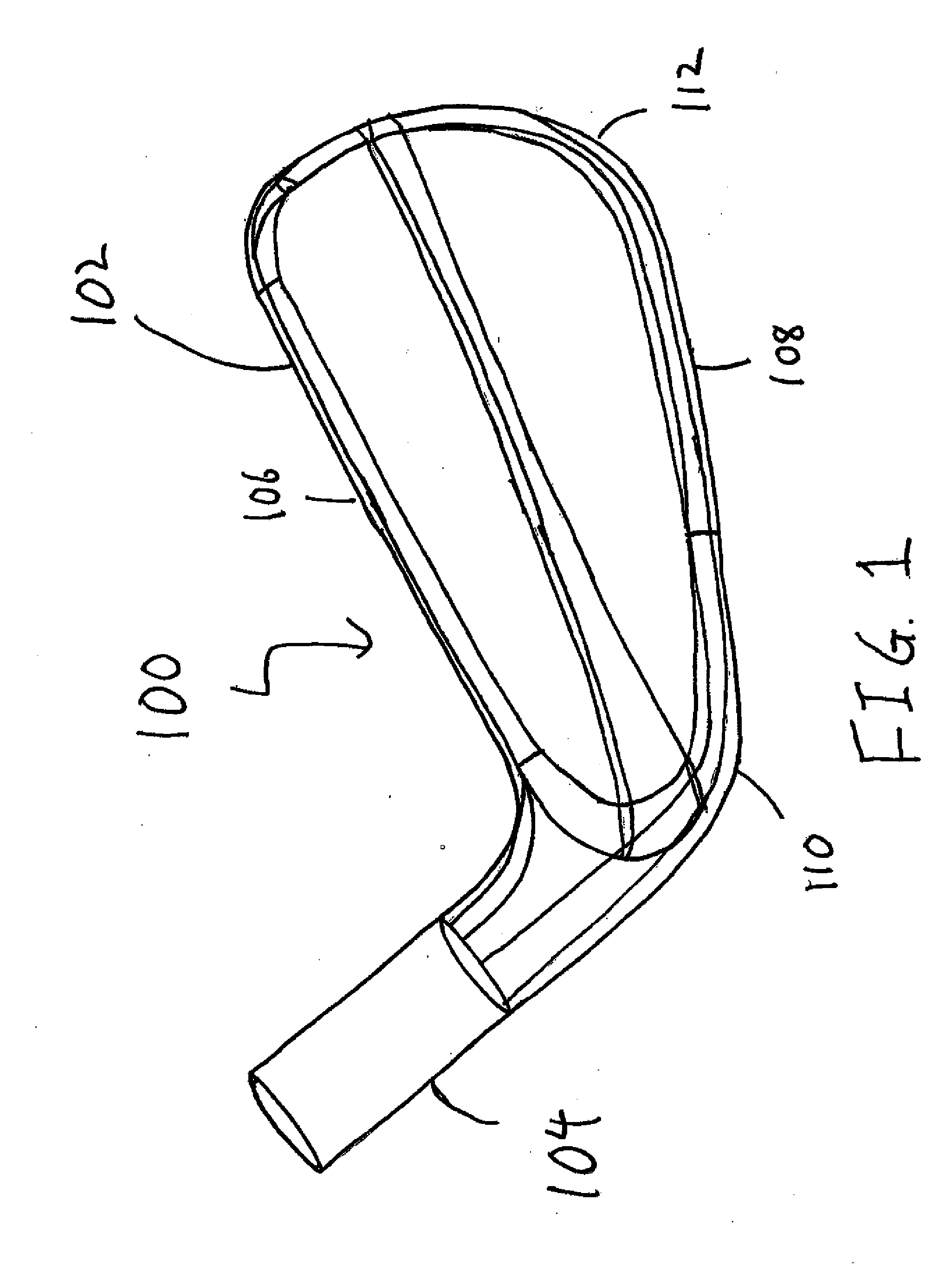
[0033]FIG. 1 of the accompanying drawings shows a perspective view of a golf club head 100 in accordance with an exemplary embodiment of the present invention. The golf club head 100 shown in FIG. 1 may generally comprise of a body portion 102 a...


PUM

PropertyMeasurementUnit
temperatureaaaaaaaaaa
flow stressaaaaaaaaaa
temperatureaaaaaaaaaa

Abstract

A co-forged iron type golf club is disclosed. More specifically, the present invention discloses a co-forged iron type golf club with the body portion made out of a first material and at least one weight adjustment portion monolithically encased within the body portion of the co-forged iron type golf club head without the need for secondary attachment or machining operations. The present invention creates of an iron type golf club head from a pre-form billet that already contains two or more materials before the actual forging process resulting in a multi-material golf club head that doesn't require any post manufacturing operations such as machining, welding, swaging, gluing, and the like.

Description

CROSS-REFERENCE TO RELATED APPLICATIONS[0001]The present application is a Continuation-In-Part of U.S. patent application Ser. No. 13 / 305,087, filed on Nov. 28, 2011, the disclosure of which is incorporated by reference in its entirety.FIELD OF THE INVENTION[0002]The present invention relates generally to a co-forged golf club head formed from two or more materials and the method of manufacture for such a golf club head. More specifically, the present invention relates to the creation of an iron type golf club head from a pre-form billet that already contains two or more materials before the actual forging process; resulting in a multi-material golf club head that doesn't require any post manufacturing operations such as machining, welding, swaging, gluing, and the like.BACKGROUND OF THE INVENTION[0003]Golf is hard! When your average golfer swings a golf club, he or she may have dramatic variations in his or her golf swing, resulting in numerous off-center hits, which result in dimi...

Claims


Application Information

Patent Timeline
31 Oct 2013
Publication
US20130288823A1
IPC
A63B53/04; B21J1/00; B21K17/00
CPC
A63B53/04; B21K17/00; B21J1/003; A63B2209/00; A63B53/047; A63B2053/0491; A63B53/0416; A63B53/0433
Inventors
HEBREO, JONATHAN A.