Devices and methods for acoustic shielding

a technology of acoustic shielding and shielding layers, which is applied in the field of acoustic shielding devices and methods, can solve the problems that shields generally do not sufficiently protect the eyes, and achieve the effects of reducing the delivery of acoustic energy to the eye, and facilitating the moisturization of the ey

Inactive Publication Date: 2012-05-10
ULTHERA INC
View PDF4 Cites 120 Cited by
  • Summary
  • Abstract
  • Description
  • Claims
  • Application Information

AI Technical Summary

Benefits of technology

[0018]In some embodiments, the shield is configured to fit over a portion of an eye and underneath at least one eyelid. In one embodiment, a therapeutic substance, which can at least one of protect the eye and facilitate in keeping the eye moist, is coated on the layer in contact with the eye. In one embodiment, the shield comprises a source of a saline solution, which can facilitate in keeping the eye moist. In one embodiment, the shield includes an optional manipulation device to aid in the insertion and removal of the shield from the body of a patient.
[0019]In various embodiments, an eye shield is configured for selectively protecting the eye from acoustic energy applied to surrounding tissue. The eye shield includes a first, second and third layer. The first layer is made of a first material with a first acoustic impedance. The second layer is in contact with and adjacent to the first layer. The second layer is made of a second material with a second acoustic impedance. In one embodiment, the first acoustic impedance is at least ten thousand times the second acoustic impedance. The third layer is made of a third material in contact with and adjacent to the second layer. The third material has a third acoustic impedance. In one embodiment, the third acoustic impedance is at least ten thousand times the second acoustic impedance. In various embodiments, the first layer, the second layer and the third layer are configured to be positioned over eye and to reduce delivery acoustic energy to the eye.

Problems solved by technology

However, such shields generally do not sufficiently protect the eyes, other non-target regions, such as, tissues, body parts, organs, medical devices, or medical implants from acoustic energy during an ultrasound treatment or imaging procedure.

Method used


Image

  • Devices and methods for acoustic shielding
  • Devices and methods for acoustic shielding
  • Devices and methods for acoustic shielding

Examples


example 1

[0110]The following example is intended to be a non-limiting embodiment of the invention.

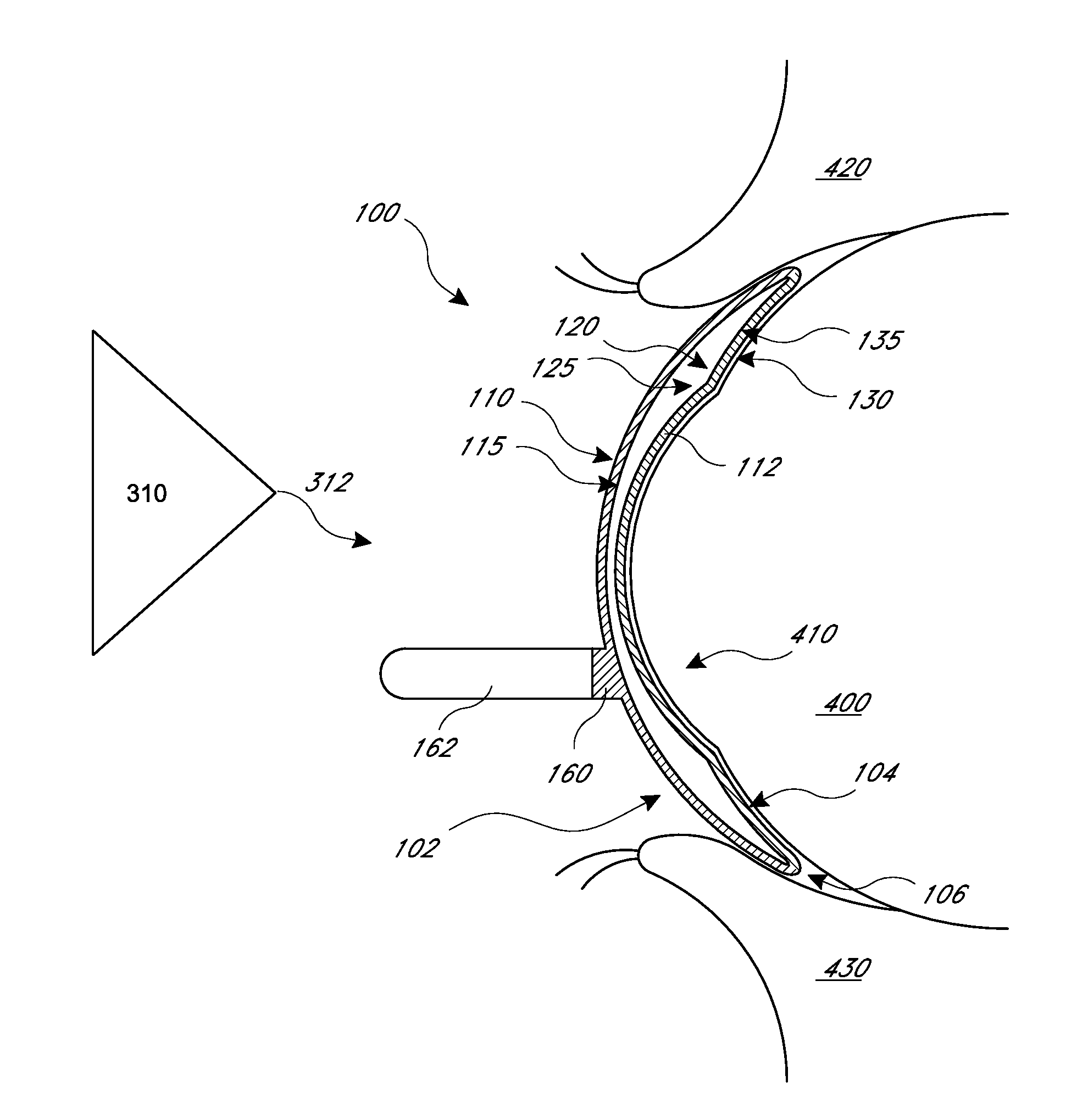
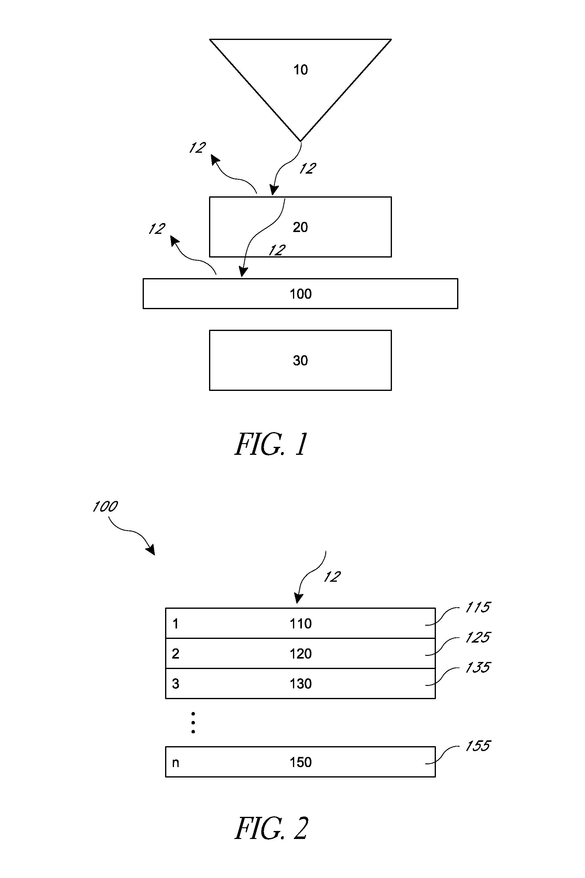
[0111]As illustrated at FIGS. 13 and 14, it was experimentally verified that an embodiment of a multi-layered shield 100, which was placed between various ultrasound procedure systems 310—and non-target region 30, reduced or eliminated the transmission of ultrasound waves 12 to a non-target region 30. In the experiment, the shield 100 was constructed of a multi-layer stack of stainless steel, air, and stainless steel with a total thickness 1.40 mm. The shield 100 had a first layer 110 made of first material 115 stainless steel, a second layer 120 made of second material 125 air, and a third layer 130 made of third material 135 stainless steel. The purpose of the experiment was to quantify the residual level of acoustic power that could pass from a superficial ultrasound transducer through a multi-layered stainless steel layers into a non-target region 30 with sensors to measure ultrasonic transm...


PUM


Abstract

Acoustic shielding system and method for protecting and shielding non-targeted regions or tissues that are not intended to be treated by ultrasonic procedures from acoustic energy using a shield. In some embodiments, the shield comprises multiple layers made of one or more materials with one or more acoustic impedances. In some embodiments a multilayered shield includes materials with relatively different acoustic impedance levels. In some embodiments, the shield includes active components such as energy diversion devices, heating, cooling, monitoring, and/or sensing. In some embodiments, the shield is configured to protect an eye, mouth, nose or ear while allowing the ultrasound to treat the surrounding tissue. One embodiment of an eye shield is configured to fit under at least one eyelid and over a portion of the eye.

Description

CROSS-REFERENCE TO RELATED APPLICATIONS[0001]This application claims the benefit of priority from U.S. Provisional Application No. 61 / 411,251 filed on Nov. 8, 2010, which is incorporated by reference in its entirety herein.BACKGROUND[0002]1. Field[0003]Embodiments of the present invention generally relate to systems and methods for performing various treatments and / or imaging procedures safely and effectively by focusing on targeted tissue while shielding or protecting a non-targeted region. Cosmetic eye shields are provided in several embodiments.[0004]2. Description of the Related Art[0005]In certain instances, eye shields can protect a patient's eyes during various surgical procedures in which scalpels, electro-cauterizers or lasers are used to carry out the surgical procedures. Some eye shields protect the eyes from direct exposure to intense light from a light source during eye surgery, or from electron beams during electron beam treatment of eyelid tumors. However, such shield...

Claims


Application Information

Patent Timeline
Patent Type & Authority Applications(United States)
IPC IPC(8): A61F5/37
CPCA61N7/00G10K11/04A61B6/107A61B8/00A61B6/4423A61B3/00G10K11/168A61F9/04A61B2019/4054A61B8/44A61B2019/4045A61F9/00A61B19/40A61B2019/4072A61F9/045A61B90/04A61B2090/0445A61B2090/0454A61B2090/0472
Inventor BARTHE, PETER G.SLAYTON, MICHAEL H.EMERY, CHARLES D.
Owner ULTHERA INC
Why Eureka
Try Eureka