Method and system for crystallization and x-ray diffraction screening

a technology of x-ray diffraction and crystallization chamber, applied in the field of nano-fluidic systems, can solve the problems of complex process, time-consuming, and difficulty in growing diffraction-quality crystals, and achieve the effect of reducing the size of the crystallization chamber and facilitating the access to diffraction data

Inactive Publication Date: 2009-06-11
FLUIDIGM CORP
View PDF12 Cites 115 Cited by
  • Summary
  • Abstract
  • Description
  • Claims
  • Application Information

AI Technical Summary

Benefits of technology

[0012]Numerous benefits are achieved using the present invention over conventional techniques. For example, an embodiment according to the present invention provides a reduction in the size of the crystallization chamber in comparison to conventional devices. Additionally, embodiments of the present invention provide for faster access to diffraction data than available using conventional crystallization techniques. Furthermore, some embodiments utilize reduced quantities of samples and reagents since determination of structure can be performed from minute quantities of material and diffraction data can be obtained in situ from most or all of the crystals present in a crystallization screen. Moreover, the diffraction quality of crystals can be measured before handling or cryoprotection. In a particular embodiment, diffraction data can be used to make decisions on which crystals are suitable for further analysis rather than visual assessment. Depending upon the embodiment, one or more of these benefits may exist. These and other benefits have been described throughout the present specification and more particularly below.

Problems solved by technology

Obtaining useful X-ray diffraction data, however, is complicated by the difficulty of growing diffraction-quality crystals, the mechanical fragility of macromolecular crystals and the accompanying care with which the crystals must be handled, and the innate interference of the device and milieu suspending the macromolecular crystal in the X-ray beam.
Current processes for performing all of the steps from crystallization to successful diffraction are complex and time consuming.
Although numerous designs have been advanced to provide for in situ x-ray diffraction of macromolecular crystals, problems are present in these designs.

Method used


Image

  • Method and system for crystallization and x-ray diffraction screening
  • Method and system for crystallization and x-ray diffraction screening
  • Method and system for crystallization and x-ray diffraction screening

Examples


Embodiment Construction

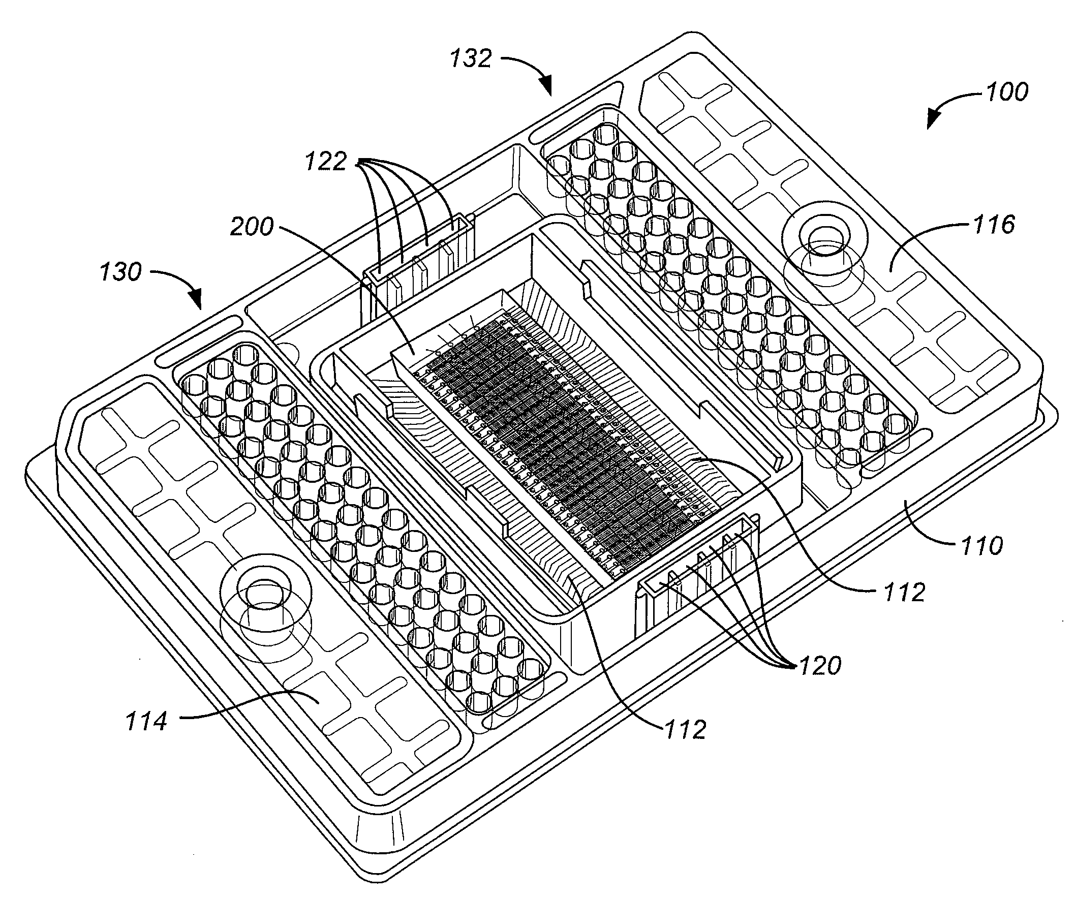
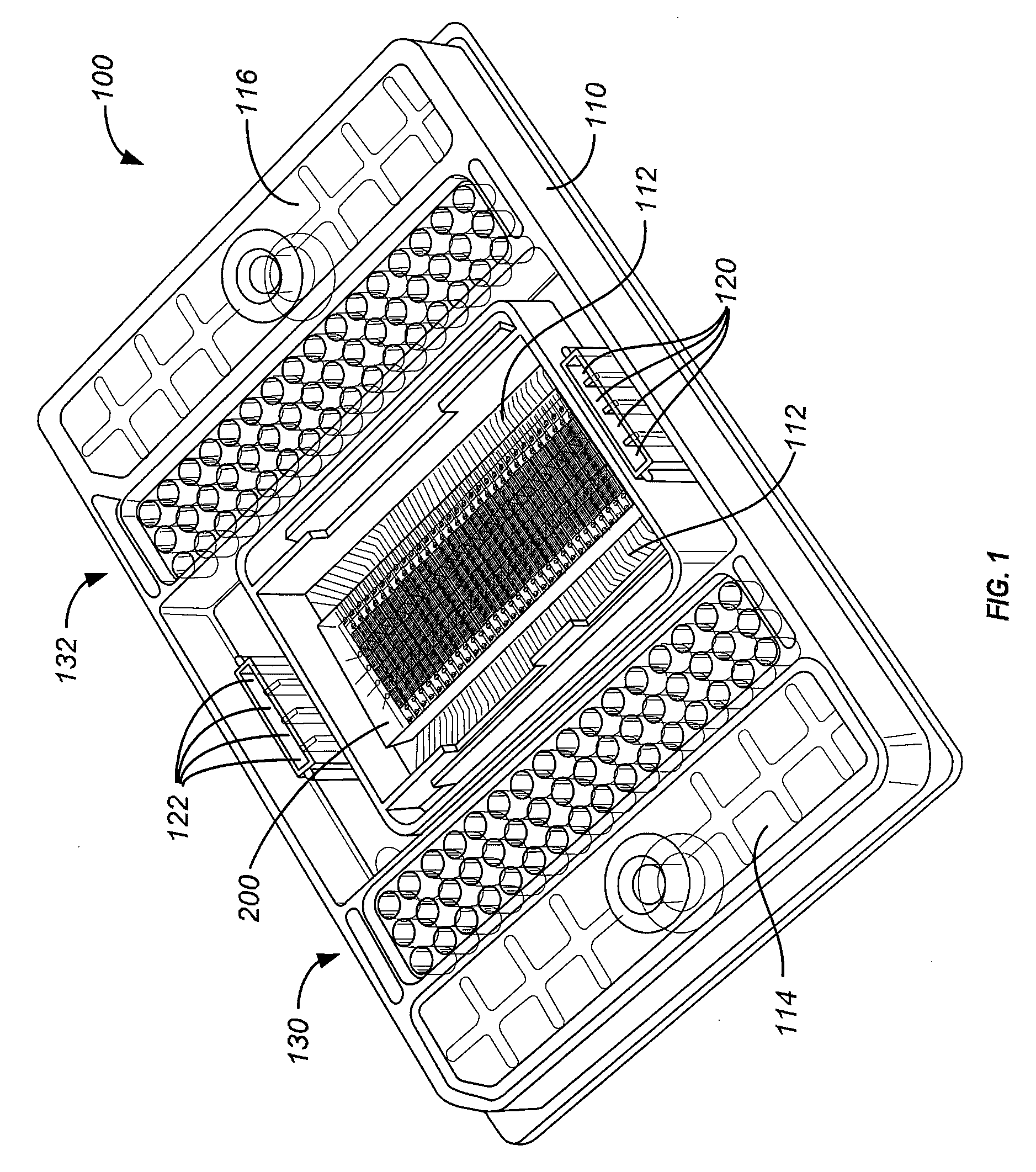
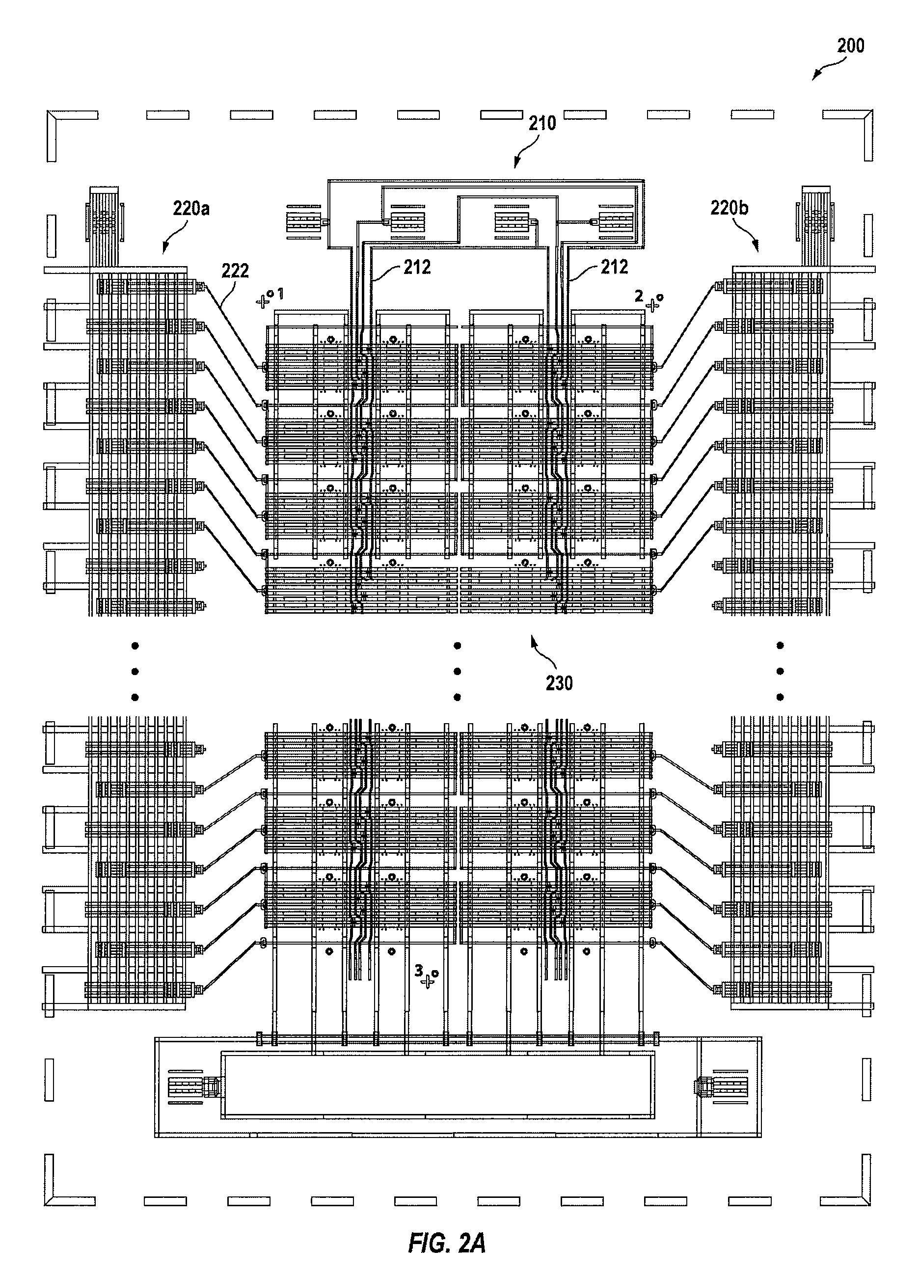
[0030]Microfluidic crystallization chips that have been used in or proposed for use in crystallography studies include those described in WO / 05056813 and WO / 04104228. Embodiments of the present invention use such microfluidic screening systems to obtain x-ray diffraction data from many or all crystallization experiments in a particular microfluidic device (chip or biochip). Diffraction data obtained from such a device allows one to determine which experiments contain useful crystals on the basis of the quality of diffraction data rather than judgments of visual quality. Additionally, embodiments of the present invention use a microfluidic screening apparatus to collect data sufficient to determine the structure of the molecules from which the crystals are formed. In some embodiments, x-ray diffraction data is obtained from the crystals without the need for removal of the crystals from the screening chip. Thus, embodiments of the present invention provide devices and systems for the ...


PUM

PropertyMeasurementUnit
heightaaaaaaaaaa
thicknessaaaaaaaaaa
thicknessaaaaaaaaaa

Abstract

An integrated fluidic circuit includes a substrate layer and a first structure coupled to the substrate layer and including a plurality of channels. The first structure is configured to provide for flow of one or more materials through the plurality of channels. The integrated fluidic circuit also includes a second structure coupled to the substrate layer. The second structure includes a plurality of control channels configured to receive an actuation pressure. The integrated fluidic circuit is characterized by a thickness of less than 1.5 mm.

Description

CROSS-REFERENCES TO RELATED APPLICATIONS[0001]The present application claims benefit under 35 U.S.C. § 119(e) of U.S. Provisional Patent Application No. 60 / 928,649, filed on May 9, 2007, entitled “In situ crystallography,” and U.S. Provisional Patent Application No. 60 / 928,865, filed on May 11, 2007, entitled “In situ crystallography,” the disclosures of which are hereby incorporated by reference in their entirety for all purposes.STATEMENT AS TO RIGHTS TO INVENTIONS MADE UNDER FEDERALLY SPONSORED RESEARCH OR DEVELOPMENT[0002]Work described herein has been supported, in part, by NIH / NIGMS STTR Phase II Grant No. 2R42GM071326-02A1. The United States Government may therefore have certain rights in the invention.BACKGROUND OF THE INVENTION[0003]The present invention relates generally to nanofluidic systems. In particular, the invention provides an architecture including nanovolume crystallization chambers configured for use in x-ray crystallographic diffraction analysis systems. More p...

Claims


Application Information

Patent Timeline
Patent Type & Authority Applications(United States)
IPC IPC(8): G01N23/207
CPCG01N23/20025
Inventor FOWLER, BRIANMAY, ANDREW
Owner FLUIDIGM CORP
Why Eureka
Try Eureka