Control device, control method, and program

a control device and control method technology, applied in the direction of instruments, heating types, static/dynamic balance measurement, etc., can solve problems such as comfort drop, and achieve the effects of reducing workload, improving comfort of occupants, and low cos

Inactive Publication Date: 2013-10-31
MITSUBISHI ELECTRIC CORP
View PDF16 Cites 31 Cited by
  • Summary
  • Abstract
  • Description
  • Claims
  • Application Information

AI Technical Summary

Benefits of technology

[0010]According to the present invention, based on the difference between environmental information for the location where the occupant is located that is detected by the sensor included in the portable terminal, and environmental information that is detected by a related device that influences the environment at that position, a target value for the environmental information that is used in environment control of the related device is corrected. As a result, it is possible for the environmental information for the location where the occupant is located to automatically approach a target value. According to the present invention, it is not necessary to perform adjustment of the location of sensors as the layout of living space changes, and it is not necessary to have a number of sensors, so it is possible to reduce the workload, and to improve comfort of the occupant at low cost.

Problems solved by technology

Particularly, when there are many heat-generating objects such as a personal computer and the like in the location where the occupant is located, it is believed that the temperature of the location where the occupant is located may not drop to the set temperature, resulting in a decrease in comfort.

Method used


Image

  • Control device, control method, and program
  • Control device, control method, and program
  • Control device, control method, and program

Examples


embodiment 1

[0027]First, Embodiment 1 of the present invention will be explained.

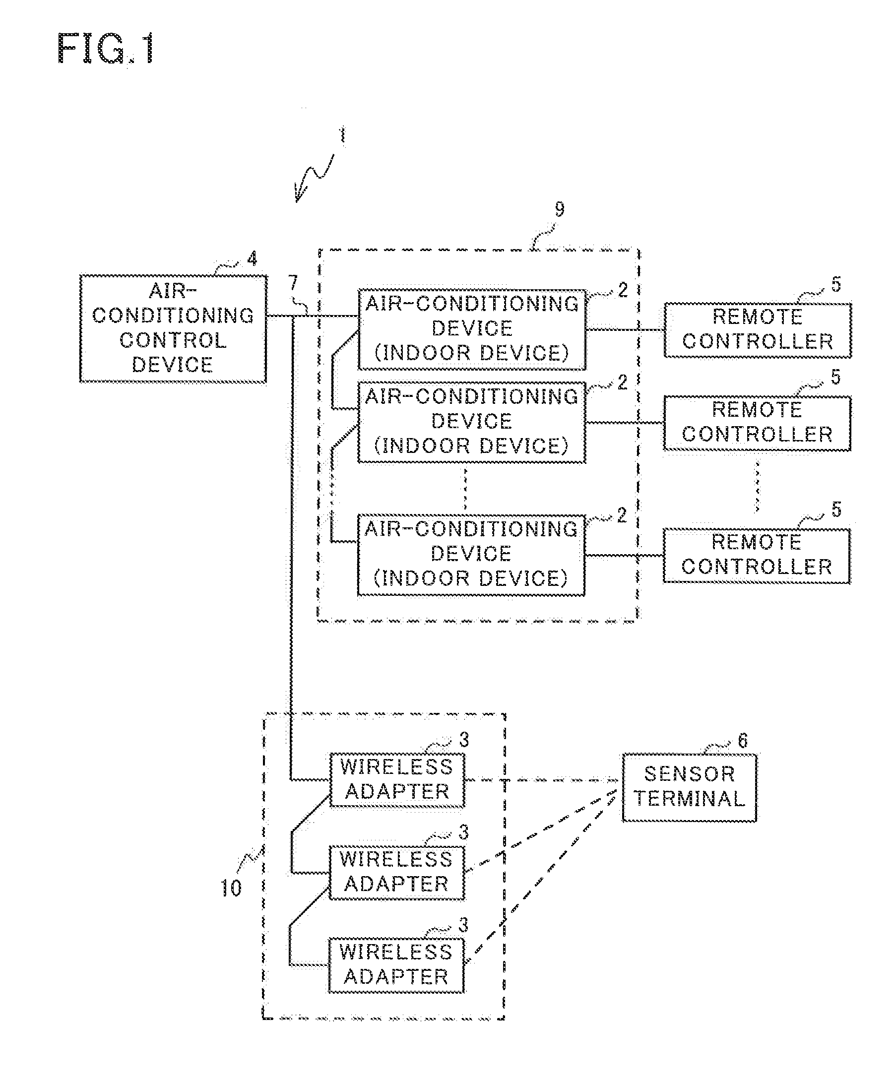
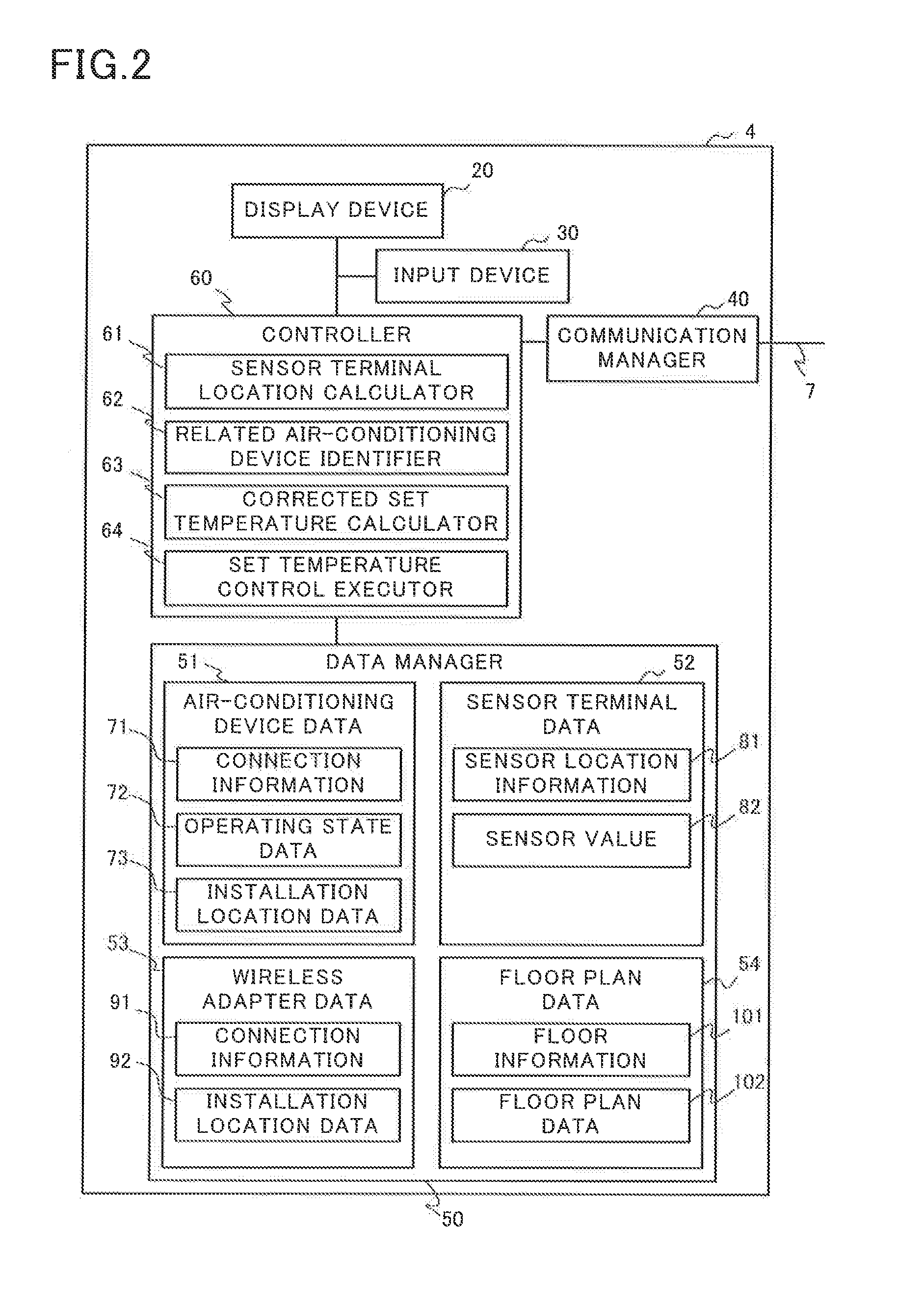
[0028]FIG. 1 illustrates a configuration of an air-conditioning system 1 of Embodiment 1 of the present invention. As illustrated in FIG. 1, the air-conditioning system 1 according to the present embodiment has a plurality of air-conditioning devices (indoor devices) 2, wireless adapters 3, an air-conditioning control device 4, remote controllers 5 and a sensor terminal 6.

[0029]The air-conditioning devices (indoor devices) 2, the wireless adapters 3 and the air-conditioning control device 4 are connected together by dedicated communication lines 7 such that communication is possible. The air-conditioning control device 4 which is not particularly illustrated in FIG. 1 is connected not only to the air-conditioning devices (indoor devices) 2, but is also connected to heat-source side devices (outdoor devices) having such as a compressor by way of the dedicated communication lines 7 such that communication is possible...

embodiment 2

[0109]Next, Embodiment 2 of the present invention will be explained.

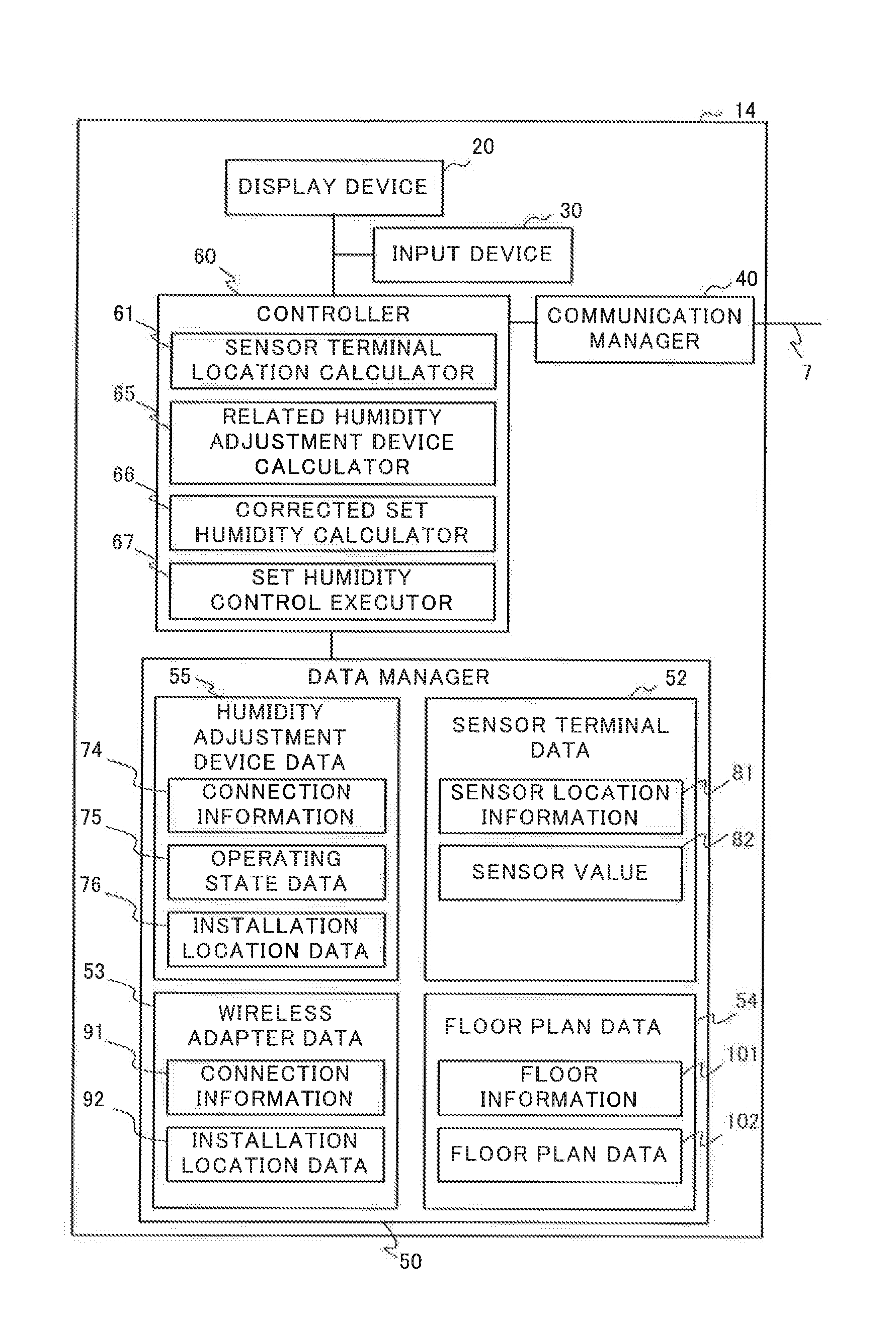
[0110]FIG. 12 illustrates a configuration of an air-conditioning system 11 according to Embodiment 2 of the present invention. As illustrated in FIG. 12, the air-conditioning system 11 according to this embodiment differs from that of Embodiment 1 in that there is a plurality of humidity adjustment devices 12 instead of the air-conditioning devices (indoor devices) 2, there is an air-conditioning control device 14 instead of the air-conditioning control device 4, and there is a remote controller 13 instead of the remote controller 5.

[0111]The humidity adjustment devices 12, wireless adapters 3 and air-conditioning control device 14 are connected by the dedicated communication lines 7 so as to be able to communicate with each other. A remote controller 13 that is capable of one operation of each of the humidity adjustment devices 12 is connected to the each of the humidity adjustment devices 12.

[0112]A plurality of t...

embodiment 3

[0124]Next, Embodiment 3 of the present invention will be explained.

[0125]FIG. 14 illustrates a configuration of an air-conditioning system 16 according to Embodiment 3 of the present invention. As illustrated in FIG. 14, the air-conditioning system 16 according to this embodiment differs from that of Embodiment 1 in that provided are a plurality of ventilation devices 17 instead of a plurality of the air-conditioning devices (indoor devices) 2, an air-conditioning control device 19 instead of the air-conditioning control device 4, and remote controllers 18 instead of the remote controllers 5.

[0126]The ventilation devices 17, wireless adapters 3 and air-conditioning control device 19 are connected using the dedicated communication lines 7 so that communication with each other is possible. A remote controller 18 that is capable of one operation of each of the ventilation devices 17 is connected to the each of the ventilation devices 17.

[0127]The ventilation devices 17 are each locate...


PUM


Abstract

A sensor terminal location calculator calculates the location of a sensor terminal based on the distance to the sensor terminal obtained by each of a plurality of wireless adapters installed in a living space. Based on the calculated sensor terminal location and installation location information for each air-conditioning device (indoor device), a related air-conditioning device identifier identifies from among the plurality of air-conditioning devices (indoor devices), a related device that influences the environment in the vicinity of the sensor terminal. Based on the difference between the temperature detected by the identified related device and the temperature detected by the sensor, a corrected set temperature calculation unit corrects a target value for the temperature used by the related device for environmental control. A set temperature control executor controls the related device based on the corrected target value.

Description

TECHNICAL FIELD[0001]The present invention relates to a control device, a control method and a program for controlling a plurality of air-conditioning devices that are installed at different locations in a living space in a home, a building or the like.BACKGROUND ART[0002]With an air-conditioning device that is located in a building, the room temperature is typically controlled based on the temperature that is detected by a temperature sensor that is installed near an air intake, or a temperature sensor inside a remote control that is located on a wall and used for operating the air-conditioning device.[0003]In this case, when the location where an occupant is actually located is distant from the installation location of the temperature sensor, the temperature of the location where the occupant is located sometimes does not obtain the set temperature. Particularly, when there are many heat-generating objects such as a personal computer and the like in the location where the occupant...

Claims


Application Information

Patent Timeline
Patent Type & Authority Applications(United States)
IPC IPC(8): G05D23/19
CPCG05D23/193G05D23/1905F24F11/30F24F2110/10F24F11/62F24F11/56F24F11/52F24F11/46F24F11/64
Inventor ISHIZAKA, TAICHI
Owner MITSUBISHI ELECTRIC CORP
Why Eureka
Try Eureka