
Separating Device

a separation device and nozzle technology, applied in the direction of separation processes, mechanical equipment, machines/engines, etc., can solve the problems of miniaturization of pressure loss at the nozzle, and achieve the effects of increasing spring force, uniform separation, and increasing fluid volume flow

Inactive Publication Date: 2013-11-07
MANN HUMMEL GMBH
View PDF0 Cites 3 Cited by
  • Summary
  • Abstract
  • Description
  • Claims
  • Application Information

AI Technical Summary

Benefits of technology

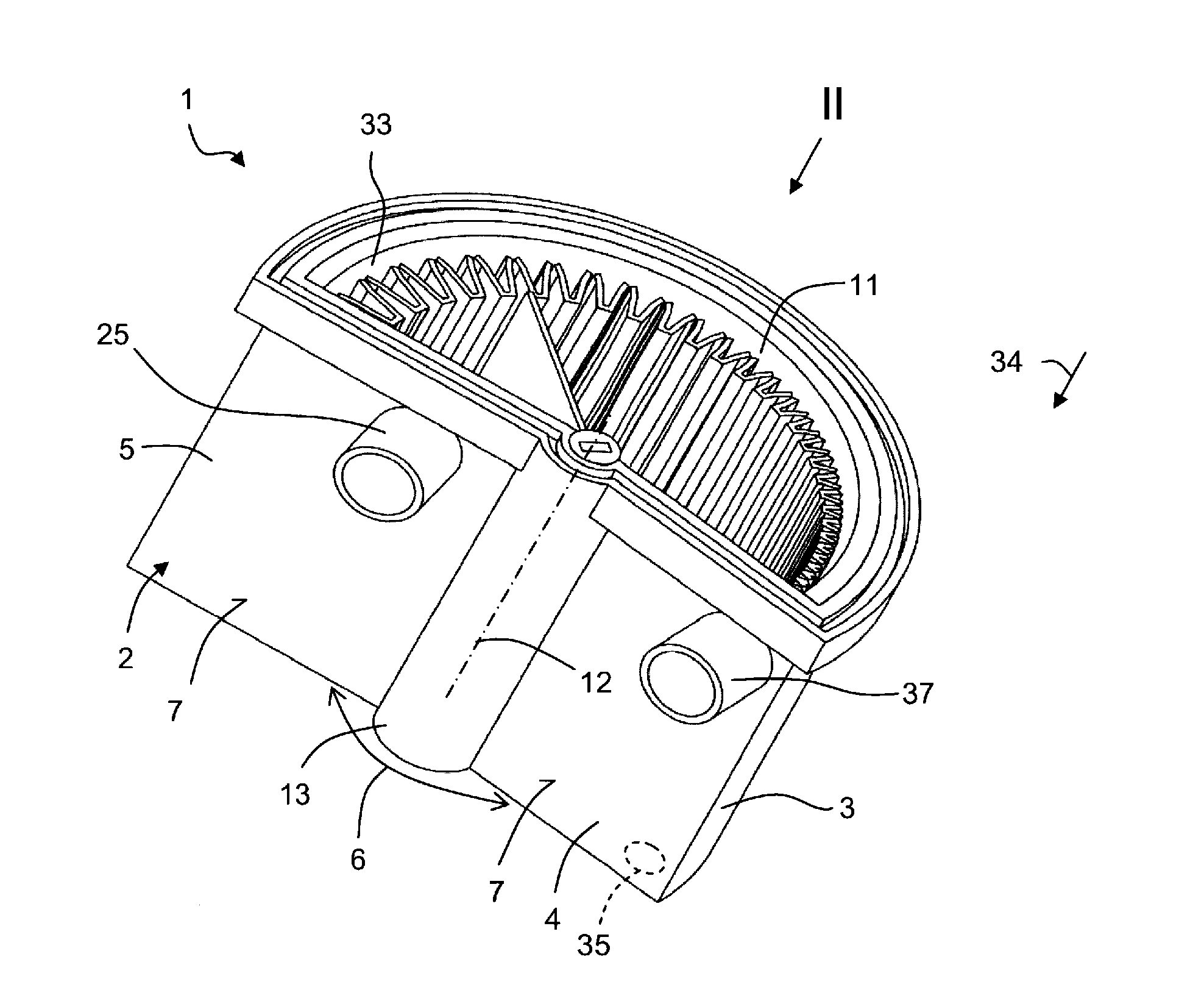
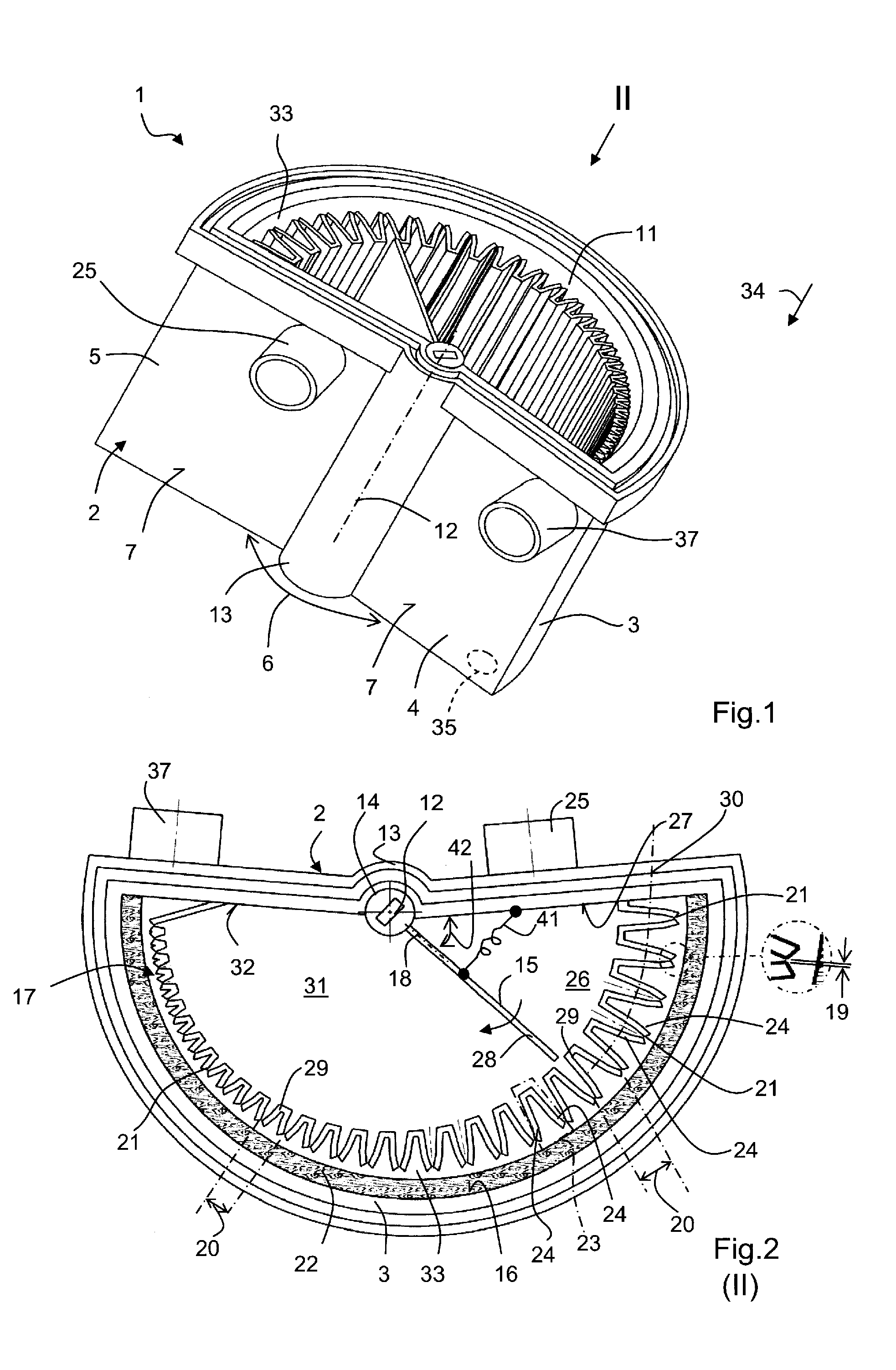
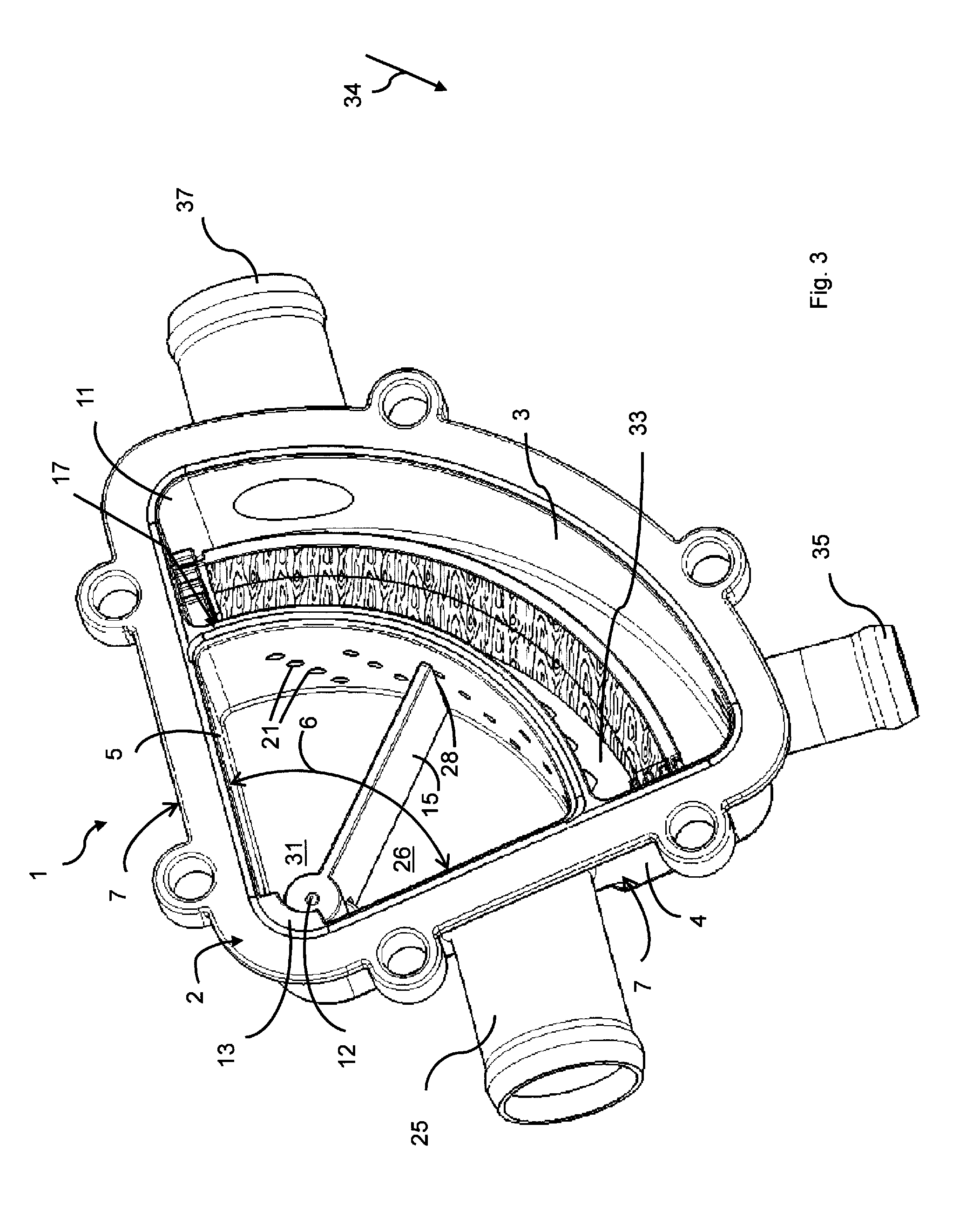
This patent describes a device that separates particles from a fluid flow. The device includes a flap that can adjust the number of nozzles through which the fluid passes. The flap is pivotally supported about a center point of the device and extends up to a partition between the nozzles to seal them from each other. The nozzles are arranged close enough to each other that the velocity of the fluid exiting them remains constant, regardless of changes in the volume flow. The nozzles are oriented perpendicular to the force of gravity, which enhances the separation performance of the device. Overall, the device provides a simple and reliable mechanism for achieving uniform separation of particles from a fluid flow.

Problems solved by technology

Also, a pressure loss at the nozzles can be mini-mized in this way.

Method used


Image

  • Separating Device
  • Separating Device
  • Separating Device

Examples


Embodiment Construction

[0032]Before describing in detail embodiments that are in accordance with the present invention, it should be observed that the embodiments reside primarily in combinations of apparatus components related to a separating device. Accordingly, the apparatus components have been represented where appropriate by conventional symbols in the drawings, showing only those specific details that are pertinent to understanding the embodiments of the present invention so as not to obscure the disclosure with details that will be readily apparent to those of ordinary skill in the art having the benefit of the description herein.

[0033]In this document, relational terms such as first and second, top and bottom, and the like may be used solely to distinguish one entity or action from another entity or action without necessarily requiring or implying any actual such relationship or order between such entities or actions. The terms “comprises,”“comprising,” or any other variation thereof, are intende...


PUM

PropertyMeasurementUnit
volume flowaaaaaaaaaa
forceaaaaaaaaaa
gravityaaaaaaaaaa

Abstract

A separating device (1), in particular for a crankcase venting device of an internal combustion engine, includes an inlet (25) supplying a fluid containing particles to be separated, a baffle plate (22) separating the particles from the fluid, several nozzles (21) oriented toward the baffle plate (22), and a pivotable flap (15) that, as a function of its pivot position, fluidically connects a first number of nozzles (21) with the inlet (25) and fluidically separates from the inlet (25) a second number of nozzles (21).

Description

CROSS REFERENCE TO RELATED APPLICATIONS[0001]This application claims the benefit under 35 USC 119 of foreign patent application DE 10 2012 008 808.6 filed in Germany on May 7, 2012, and which is hereby incorporated by reference in its entirety.TECHNICAL FIELD[0002]The present invention concerns a separating device, in particular for a crankcase venting device of an internal combustion engine.BACKGROUND OF THE INVENTION[0003]In operation of an internal combustion engine, blow-by gasses are generated in the crankcase. These blow-by gasses comprise an oil-air mixture. From this mixture the oil is to be separated and collected while the air is to be supplied to an intake manifold of the internal combustion engine.[0004]For example, DE 10 2009 035 742 A1 describes an oil separating device for a crankcase of an internal combustion engine. The known separating device comprises a tubular inner part and an outer part surrounding it. The outer part has a baffle wall. The gas jets existing fro...

Claims


Application Information

Patent Timeline
Patent Type & Authority Applications(United States)
IPC IPC(8): F01M13/04
CPCF01M13/04F01M2013/0433B01D45/08B01D45/16B01D45/12B01D50/20
Inventor MELDE, MARKUSPRAHLAD, PRAVEEN
Owner MANN HUMMEL GMBH
Learn More