
Tread for the tire of a farm tractor

a tractor and tire tread technology, applied in the direction of vehicles, vehicle components, non-skid devices, etc., can solve the problems of premature tire removal, uneven tread wear, and tire wear more quickly, and achieve the effect of favorable

Active Publication Date: 2013-11-07
MICHELIN & CO CIE GEN DES ESTAB MICHELIN +1
View PDF5 Cites 4 Cited by
  • Summary
  • Abstract
  • Description
  • Claims
  • Application Information

AI Technical Summary

Benefits of technology

The present invention is aimed at improving the tire's ability to grip the field and road for a multipurpose agricultural machine like an agricultural tractor. The goal is to achieve a balance between wear resistance under engine torque and vibratory comfort on the road.

Problems solved by technology

However, these solutions have the drawback of causing more rapid wear of the short lugs relative to the long lugs, leading to irregular wear of the tread and the premature removal of the tire.
The drawback of these solutions is that they lead to more rapid wear of the tire, which is a cause of premature removal of the tire.
The dissymmetry of the design has the drawback of a fitting constraint between the left and right sides of the axle of the agricultural tractor.
Short of 20% of the tread width, the short lug has an insufficient axial width to participate effectively in traction in the field.
Moreover, too short a lug is mechanically weaker and sensitive to tearing.
Beyond 40% of the tread width, the short lug has too great an axial width that is likely to cause a geometric incompatibility with the long lugs of the symmetrical row.
Several inner grooves would be likely to diminish the rigidity of the long lug, and to make it less effective in traction and more sensitive to tearing.

Method used


Image

  • Tread for the tire of a farm tractor
  • Tread for the tire of a farm tractor
  • Tread for the tire of a farm tractor

Examples


Embodiment Construction

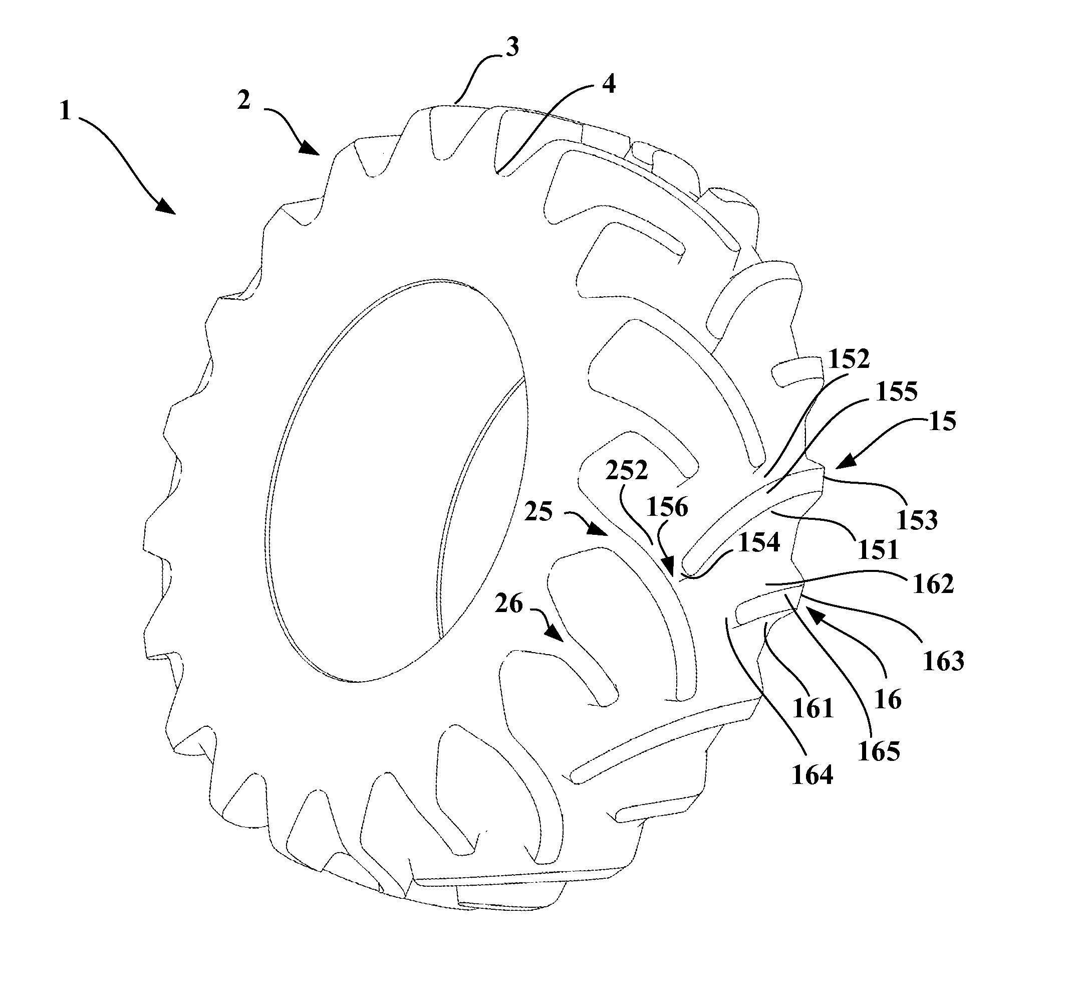
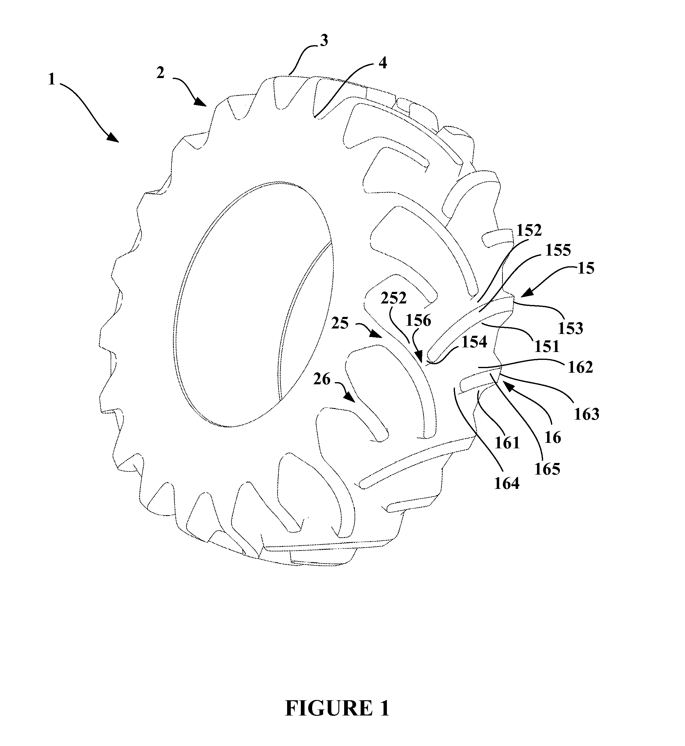
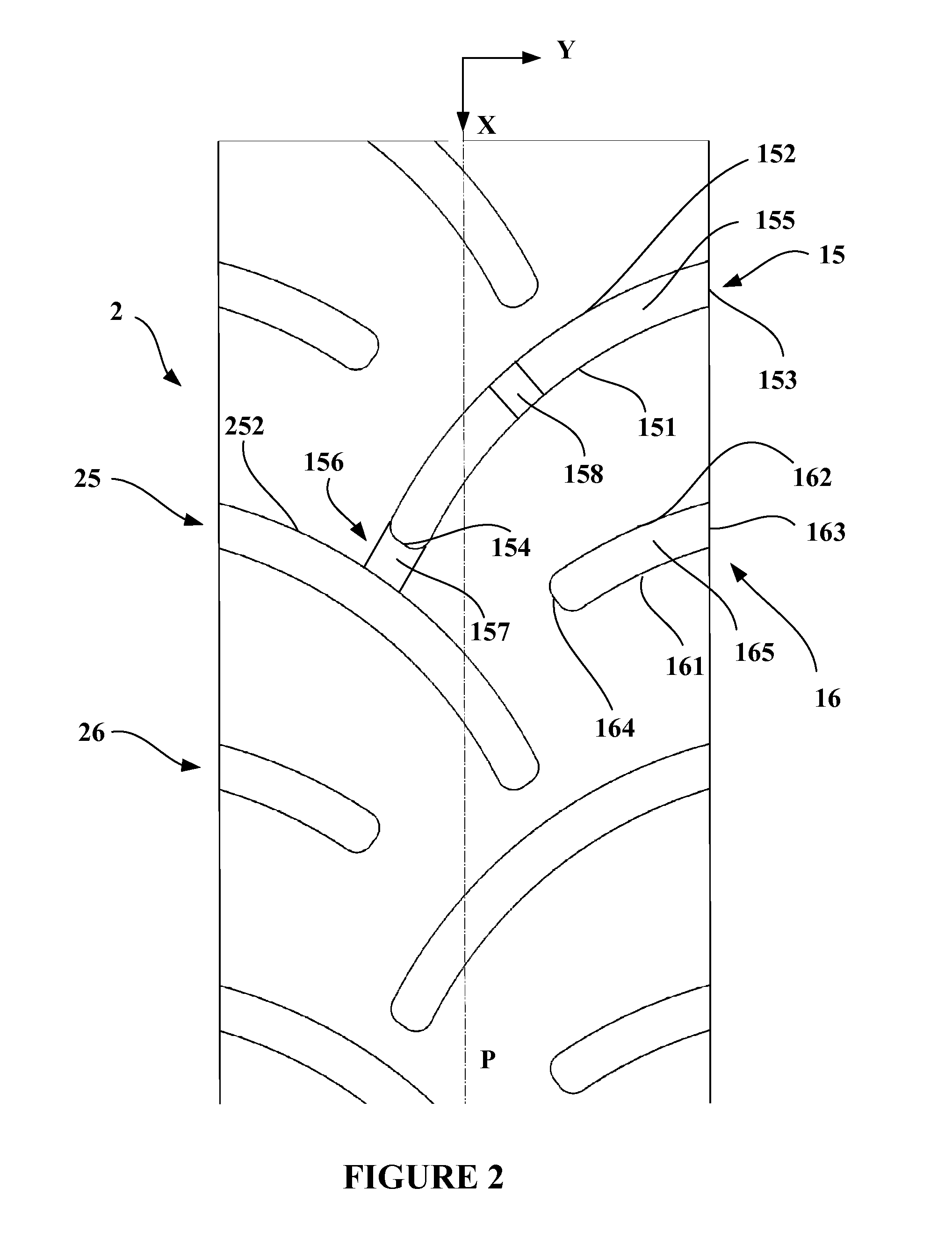
[0059]According to the invention, the axially inner end face 154 of a first long lug 15 of a row of lugs is separated from the trailing lateral face 252 of the second long lug 25 of the symmetrical row of lugs, closest to the axially inner end face of the first long lug, by an end groove 156 with a width e at least equal to 10% and at most equal to 100% of the lug height.

[0060]In the embodiment of FIG. 3, the end groove 156 is at least partly filled by an elastomeric linking element 157 extending radially from the inner surface 4 of the tread. Moreover, the long lug 15 comprises a single inner groove 158, with a width e1 and an axial distance L′1 relative to the equatorial plane P.

[0061]The contact face (155, 165) of a lug is moreover defined geometrically by its centre line m limited by the axially outer end point E and the axially inner end point I. The geometric line of the centre line m is characterized by:

[0062]the angle of inclination a of the tangent te to the centre line m a...


PUM


Abstract

A tread and tire for a multipurpose agricultural machine, that improves field traction while ensuring a satisfactory compromise with wear under engine torque and vibratory comfort on the road having a tread having a plurality of lugs distributed in a first row extending axially from a first axial end of the tread and in a second row extending axially from a second axial end of the tread, the second row differing from the first row by a symmetry relative to the equatorial plane of the tire followed by a rotation about the rotation axis of the tire, each row having an alternation of long lugs and of short lugs. The axially inner end face of a first long lug of a row of lugs is separated from the trailing lateral face of the second long lug of the symmetrical row of lugs, closest to the axially inner end face of the first long lug, by an end groove with a width at least equal to 10% and at most equal to 100% of the lug height.

Description

BACKGROUND[0001]1. Field[0002]The present invention relates to a tire for a heavy vehicle designed to run on various types of ground, and in particular the tread of such a tire.[0003]Although not limited to this application, the invention will be more particularly described with reference to a multipurpose agricultural machine that can run just as well in the fields as on the road, such as an agricultural tractor.[0004]2. Description of Related Art[0005]A tire for an agricultural tractor is designed to run on various types of ground such as the more or less compact earth of fields, the unpaved tracks for access to the fields and the paved surfaces of roads. Because of the diversity of use, in the field and on the road, a tire for an agricultural tractor, and in particular its tread designed to come into contact with the ground, must have a performance compromise between field traction, resistance to tearing, resistance to wear on the road, rolling resistance, vibratory comfort on th...

Claims


Application Information

Patent Timeline
IPC IPC(8): B60C11/13
CPCB60C11/033B60C11/0311B60C2011/0313B60C2200/08B60C11/1369
Inventor VERVAET, PATRICKROYER
Owner MICHELIN & CO CIE GEN DES ESTAB MICHELIN
Learn More