Building control unit method and controls

a technology of building control and control unit, applied in lighting and heating apparatus, heating types, instruments, etc., can solve the problems of reducing user satisfaction and/or energy-saving opportunities, confusing and frustrating tactile feedback, and user intimidation, and achieve the effect of improving tactile feedback for users

Active Publication Date: 2013-11-07
GOOGLE LLC
View PDF15 Cites 130 Cited by
  • Summary
  • Abstract
  • Description
  • Claims
  • Application Information

AI Technical Summary

Benefits of technology

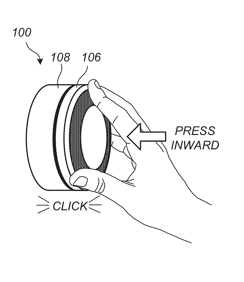
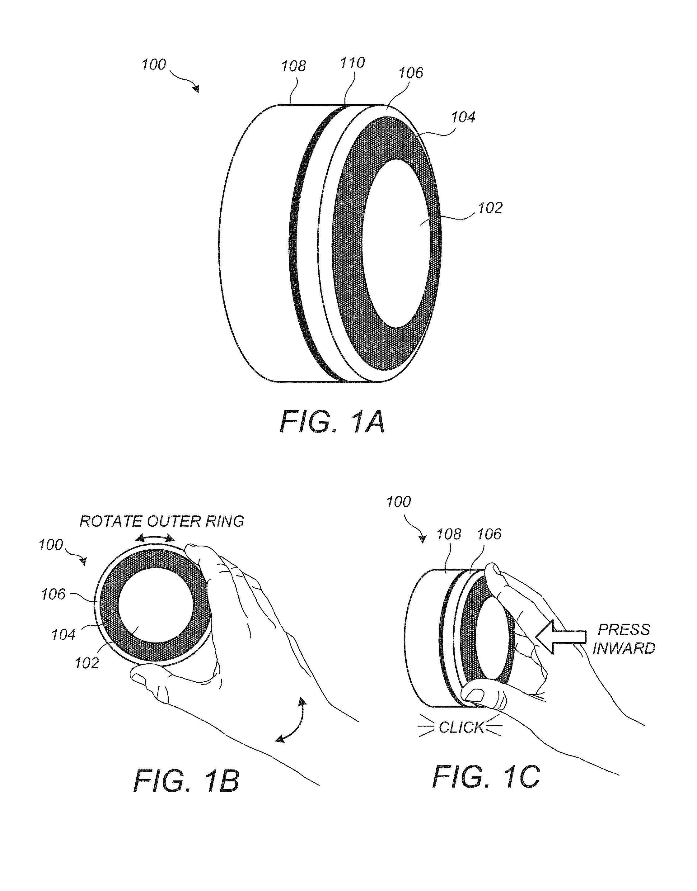
[0003]Embodiments of the invention provide thermostat controls having improved tactile feedback for a user. According to one embodiment, a thermostat is provided. The thermostat may include a bottom disk-shaped member, a switch disposed on a surface of the bottom disk-shaped member, a top disk disk-shaped member, and a ring-shaped component that is rotationally coupled with the top disk-shaped member. The ring-shaped component may be configured to track a rotational input motion of a user to allow the user to scroll between options of an electronic thermostat menuing system. A motion guiding member or assembly may op

Problems solved by technology

However, users are frequently intimidated by a dizzying array of switches and controls and/or the controls may provide confusing and frustrating tac

Method used


Image

  • Building control unit method and controls
  • Building control unit method and controls
  • Building control unit method and controls

Examples


Embodiment Construction

[0035]The subject matter of this patent specification also relates to the subject matter of the following commonly assigned applications: U.S. Ser. No. 12 / 881,430 filed Sep. 14, 2010; U.S. Ser. No. 12 / 881,463 filed Sep. 14, 2010; U.S. Prov. Ser. No. 61 / 415,771 filed Nov. 19, 2010; U.S. Prov. Ser. No. 61 / 429,093 filed Dec. 31, 2010; U.S. Ser. No. 12 / 984,602 filed Jan. 4, 2011; U.S. Ser. No. 12 / 987,257 filed Jan. 10, 2011; U.S. Ser. No. 13 / 033,573 filed Feb. 23, 2011; U.S. Ser. No. 29 / 386,021, filed Feb. 23, 2011; U.S. Ser. No. 13 / 034,666 filed Feb. 24, 2011; U.S. Ser. No. 13 / 034,674 filed Feb. 24, 2011; U.S. Ser. No. 13 / 034,678 filed Feb. 24, 2011; U.S. Ser. No. 13 / 038,191 filed Mar. 1, 2011; U.S. Ser. No. 13 / 038,206 filed Mar. 1, 2011; U.S. Ser. No. 29 / 399,609 filed Aug. 16, 2011; U.S. Ser. No. 29 / 399,614 filed Aug. 16, 2011; U.S. Ser. No. 29 / 399,617 filed Aug. 16, 2011; U.S. Ser. No. 29 / 399,618 filed Aug. 16, 2011; U.S. Ser. No. 29 / 399,621 filed Aug. 16, 2011; U.S. Ser. No. 29 / 399,...


PUM


Abstract

Embodiments of the invention provide thermostat controls having improved tactile feedback. According to one embodiment, a thermostat includes a bottom member, a switch, a top member, and a motion guiding member or assembly that operationally couples the top member with the bottom member so that the top member is inwardly pressable by a user relative to the bottom member to allow the thermostat to receive input from the user by contacting the switch with a component of the top member or the bottom member. The motion guiding member or assembly contacts the top member near its outer periphery to control the inward motion of the top member relative to the bottom member to provide the improved tactile feedback.

Description

BACKGROUND OF THE INVENTION[0001]While substantial effort and attention continues toward the development of newer and more sustainable energy supplies, the conservation of energy by increased energy efficiency remains crucial to the world's energy future. According to an October 2010 report from the U.S. Department of Energy, heating and cooling account for 56% of the energy use in a typical U.S. home, making it the largest energy expense for most homes. Along with improvements in the physical plant associated with home heating and cooling (e.g., improved insulation, higher efficiency furnaces), substantial increases in 5 energy efficiency can be achieved by better control and regulation of home heating and cooling equipment. By activating heating, ventilation, and air conditioning (HVAC) equipment for judiciously selected time intervals and carefully chosen operating levels, substantial energy can be saved while at the same time keeping the living space suitably comfortable for its...

Claims


Application Information

Patent Timeline
IPC IPC(8): G05D23/19
CPCF24F2013/207G05D23/1902H01H2300/03Y02B90/20Y04S20/14
Inventor FILSON, JOHN B.DANIELS, ERIC B.FADELL, ANTHONY M.ROGERS, MATTHEW LEE
Owner GOOGLE LLC
Why Eureka
Try Eureka