

Liquid ejecting head unit and liquid ejecting apparatus
a liquid ejecting head and ejecting apparatus technology, applied in the direction of printing, inking apparatus, etc., can solve the problems of difficult to shorten the width of the recording head unit, the support member in a direction perpendicular to the alignment direction of the recording head cannot be shortened, and the pressure loss can be reduced, so as to reduce the flow resistance
- Summary
- Abstract
- Description
- Claims
- Application Information
AI Technical Summary
Benefits of technology
Problems solved by technology
Method used
Image

Examples
first embodiment
[0046]Hereinafter, the invention will be described in detail based on embodiments of the invention. An ink jet recording head unit is an example of a liquid ejecting head unit and is simply called a “head unit” as well. An ink jet recording head is an example of a liquid ejecting head and is simply called a “head” as well.
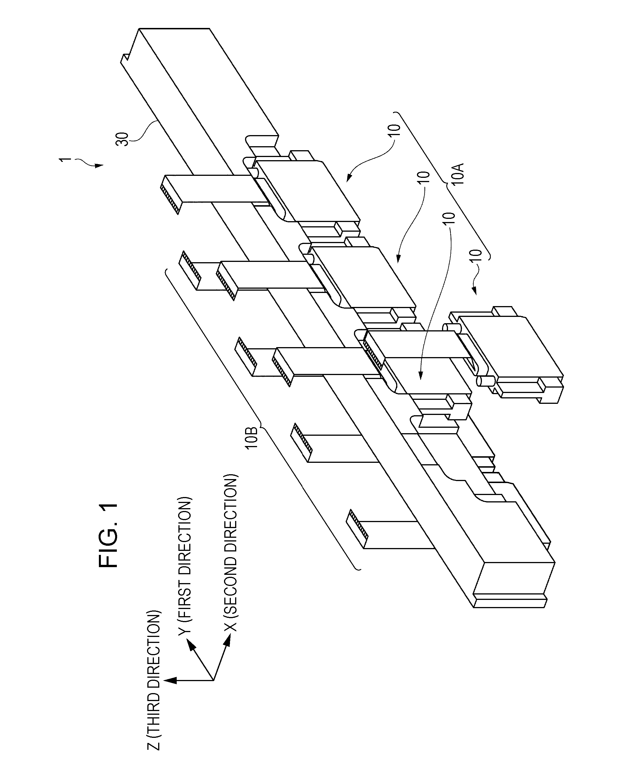
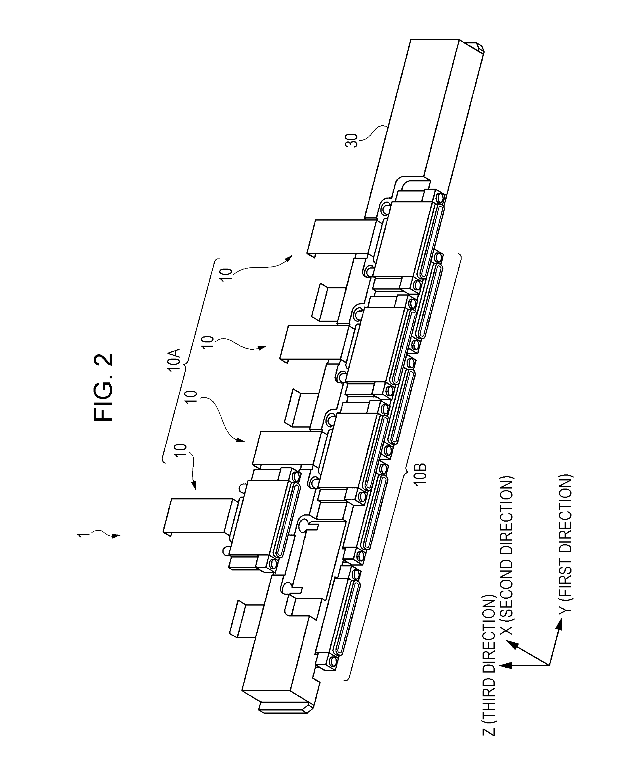
[0047]FIG. 1 is a schematic perspective view illustrating the top face side of a head unit according to a first embodiment of the invention, and FIG. 2 is a schematic perspective view illustrating the bottom face side of the head unit according to the embodiment. The top face side of the head unit is a face on the opposite side to a liquid ejecting surface of a head to be explained later, and the bottom face side of the head unit is a face on the liquid ejecting surface side.
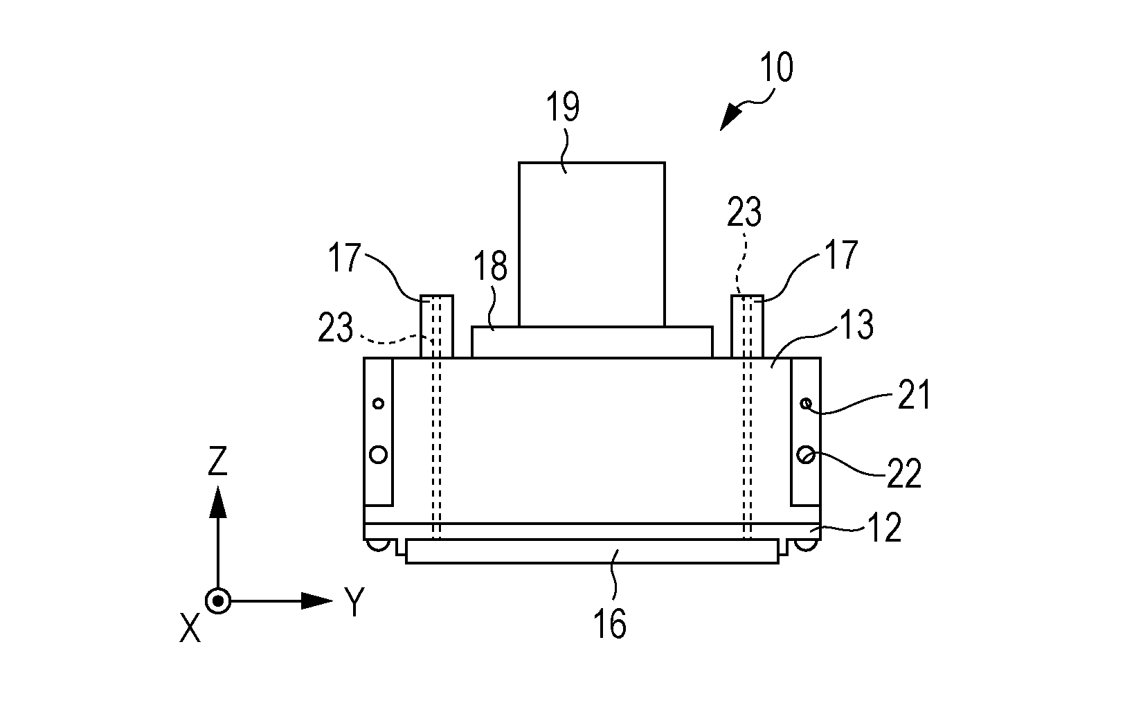
[0048]A head unit 1 includes a plurality of heads 10 and a holding member 30 that holds the heads 10.
[0049]The heads 10 form two head rows configured of head rows A and B in each of which four ...
second embodiment
[0111]In the first embodiment, the ink channel 23 is open in the insertion portion 17 and is connected with the ink tube 25 being inserted into the connection channel 32; however, the invention is not limited thereto.
[0112]FIG. 16 is an enlarged cross-sectional view illustrating a principal portion of a connecting portion between the head 10 and the holding member 30 according to a second embodiment of the invention. Note that the same elements as those in the first embodiment will be given the same reference numerals and duplicate description thereof Will be omitted.
[0113]The insertion portion 17 according to this embodiment is directly connected with the connection channel 32. That is, unlike in the first embodiment, the insertion portion 17 is connected with the connection channel 32 without using the ink tube 25. The connection channel 32 communicates with a channel 61 of the channel member 60 that is provided to the holding member 30, for example. The channel 61 of the channel ...
third embodiment
[0115]An ink jet recording apparatus as an example of a liquid ejecting apparatus including the head unit 1 according to the first embodiment will be described. FIG. 17 is a schematic perspective view of an ink jet recording apparatus according to a third embodiment of the invention. Note that the same elements as those in the first embodiment are given the same reference numerals and duplicate description thereof will be omitted.
[0116]An ink jet recording apparatus I is what is known as a line type recoding apparatus in which the head unit 1 is fixedly installed and printing is performed by transporting an ejection-target medium such as a recording sheet. To be more specific, the ink jet recording apparatus I includes the head unit 1, a main apparatus body 2, and a transport unit 4 that transports an ejection-target medium S.
[0117]The head unit 1 is installed in the main apparatus body 2 so that the ejection-target medium S is transported in a transport direction (X direction) orth...
PUM
 Abstract
Description
Claims
Application Information