Check patentability & draft patents in minutes with Patsnap Eureka AI!

Redundant control device and network system

a control device and network system technology, applied in data switching networks, frequency-division multiplexes, instruments, etc., can solve problems such as useless switchover, time difference for detecting port state generation, and unnecessary switchover

Inactive Publication Date: 2013-11-07
ALAXALA NETWORKS
View PDF12 Cites 13 Cited by
  • Summary
  • Abstract
  • Description
  • Claims
  • Application Information

AI Technical Summary

Benefits of technology

The present invention introduces a technique that prevents a redundant network repeater from implementing unnecessary switchovers and minimizes delays while doing so. This helps to improve the efficiency of the network and to prevent unnecessary downtime for maintenance.

Problems solved by technology

In the case of using a redundant switching technique for performing a priority determination through a comparison of the number of effective ports, it is recognized as a problem that when states of downstream devices or lines change, a time difference for detecting a port state is generated among a plurality of redundant network repeaters and a useless switchover is caused by the above-described fact.
Comparison results about the number of effective ports are temporarily exchanged among network repeaters, and as a result, a useless switchover is caused as a problem.
As if the layer in a network system in which a loop occurs when a plurality of redundant network repeaters are capable of communication at the same time, the above-described problems are dominantly caused and the useless switchover brings about a communication interruption.
However, even when the switchover ought to be originally performed, it is delayed and expansion of the communication interruption time is brought about.

Method used


Image

  • Redundant control device and network system
  • Redundant control device and network system
  • Redundant control device and network system

Examples


first embodiment

[0025]In the present embodiment, there will be described an example in which when mutually grasping connection states via downstream devices, both redundant network repeaters determine that a failure occurs in which portion in a network and suppress switching delay, thereby preventing useless switching.

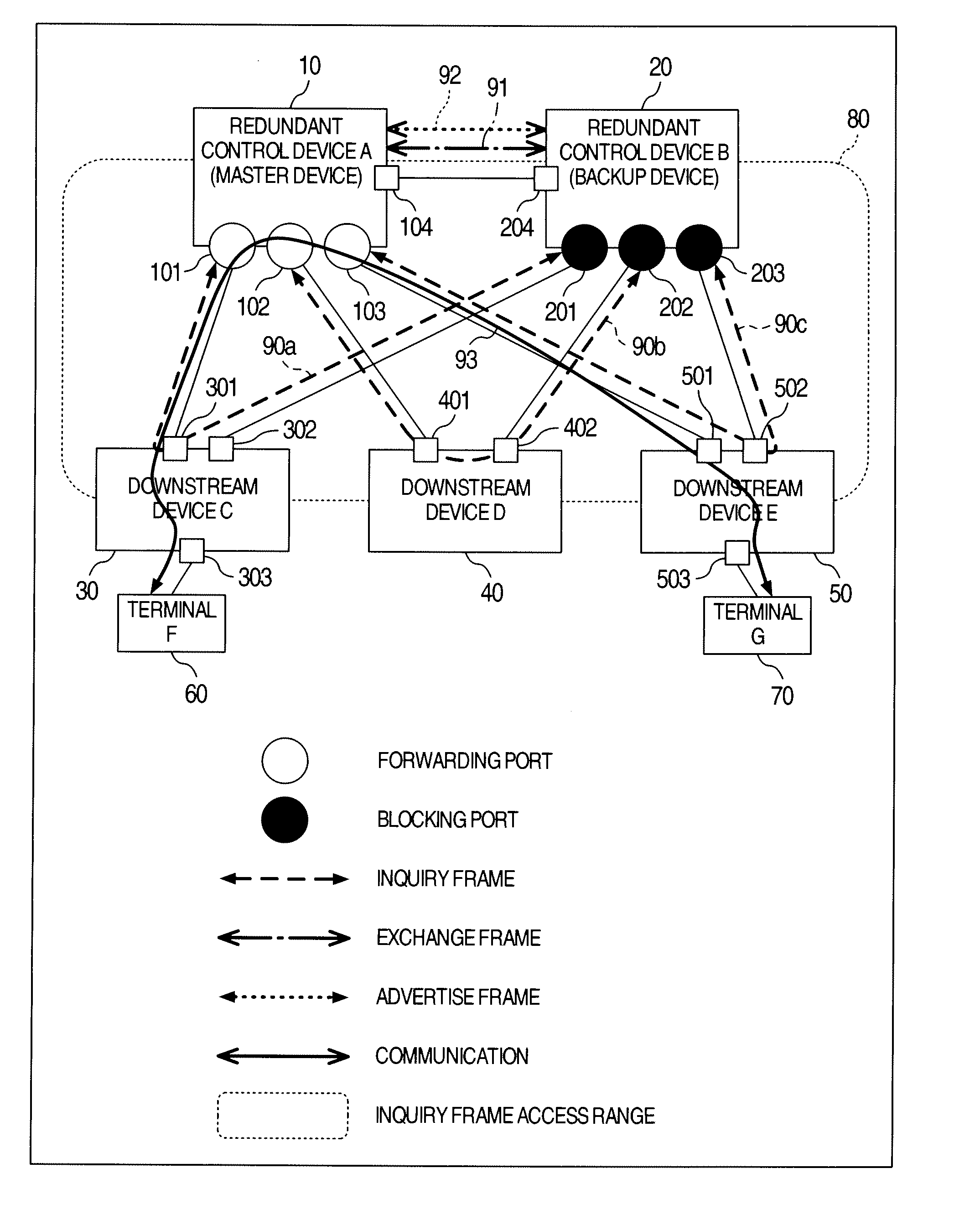
[0026]FIG. 1 illustrates configurations of the redundant network repeater and system thereof according to the present embodiment. In the present embodiment, the redundant network repeater having a switching function is called a redundant control device. In the network configuration example of FIG. 1 the redundant control device A10 and redundant control device B20 as a network repeater each make up a redundant configuration. The redundant control device A10 has ports 101 to 103, and is connected to downstream devices C30 to E50 through each line such as the Ethernet (registered trademark) via each port. In the same manner, the redundant control device B20 has ports 201 to 203, and is ...

second embodiment

[0088]In the present embodiment, there will be described an example where three redundant control devices being a network repeater which implements a redundant switching function are connected to each other. Even if three redundant control devices or more are connected to each other, the same operations as those of the first embodiment are performed. Previously, the redundant control device needs to carefully grasp a connection state and determine whether a switchover is required.

[0089]FIG. 11 is an example of a system configuration in which three redundant control devices are connected to each other. FIG. 11 mainly differs from FIG. 1 in that a redundant control device H90 is freshly added to FIG. 1. The redundant control device H90 has a plurality of ports, and is connected to the downstream devices C to E, respectively. In addition, the redundant control devices A10, B20, and H90 are directly connected to each other, respectively, and transmit and receive an exchange frame and an...


PUM


Abstract

Network repeaters which each implement a redundant switching function previously grasp connection states of ports of a network system by using an inquiry frame and an exchange frame. At the time when a line is broken, when actively confirming a state of a port connected to a port in which a line is broken via a downstream device, the network repeaters each grasp that which portion of the line is broken and determine whether a switchover is required. Through the process, the network repeaters each prevent a useless switchover such as switching-back immediately after the switchover, and at the same time since a mechanism of waiting for a given length of times is not required, they each perform a fast switchover.

Description

INCORPORATION BY REFERENCE[0001]The present application claims priority from Japanese application JP2011-264228 filed on Dec. 2, 2011, the content of which is hereby incorporated by reference into this application.BACKGROUND OF THE INVENTION[0002]The present invention relates to a redundant control device and a network system, more particularly, to a master switching control technique of the redundant control device.[0003]In general, in a network, a redundant configuration is adopted in such a manner that communication is not stopped due to the fact that a line or device is broken. In a plurality of redundant network repeaters, respective network repeaters are connected through a plurality of downstream devices and ports. Further, some network repeaters each having the large number of effective ports (the number of linked-up ports among the ports connected to the downstream devices) operate as an operation system. The above-described technique is disclosed, for example, in JP-A-2005...

Claims


Application Information

Patent Timeline
Patent Type & Authority Applications(United States)
IPC IPC(8): H04L1/22H04L45/60H04L45/586
CPCH04L1/22G06F11/2007G06F2201/845
Inventor FUKUZAKI, SHOHEIWATANABE, KEN
Owner ALAXALA NETWORKS
Features
  • R&D
  • Intellectual Property
  • Life Sciences
  • Materials
  • Tech Scout
  • Unparalleled Data Quality
  • Higher Quality Content
  • 60% Fewer Hallucinations
Learn More