Depth testing device

a testing device and depth technology, applied in measurement devices, measurement gauges, instruments, etc., can solve the problems of ensuring the cutting precision of the screw, the accuracy of the test results, and the inability to produce precise test results using calipers

Active Publication Date: 2013-11-14
FULIAN PRECISION ELECTRONICS (TIANJIN) CO LTD
View PDF10 Cites 16 Cited by
  • Summary
  • Abstract
  • Description
  • Claims
  • Application Information

AI Technical Summary

Benefits of technology

[0008]FIG. 1 is an exploded view of a depth testing device for testing the depth of screw drives in accordance with an exemplary embodiment; the depth testing device includes a supporting assembly, a testing assembly, and a calibrating assembly having a calibrating element.

Problems solved by technology

However, testing using calipers may not produce precise results.
However, since the screw is small, it is difficult to assure the cutting precision of the screw, thereby the test results are not precise either.
Furthermore, cutting the screw is tedious work.

Method used


Image

  • Depth testing device
  • Depth testing device
  • Depth testing device

Examples


Embodiment Construction

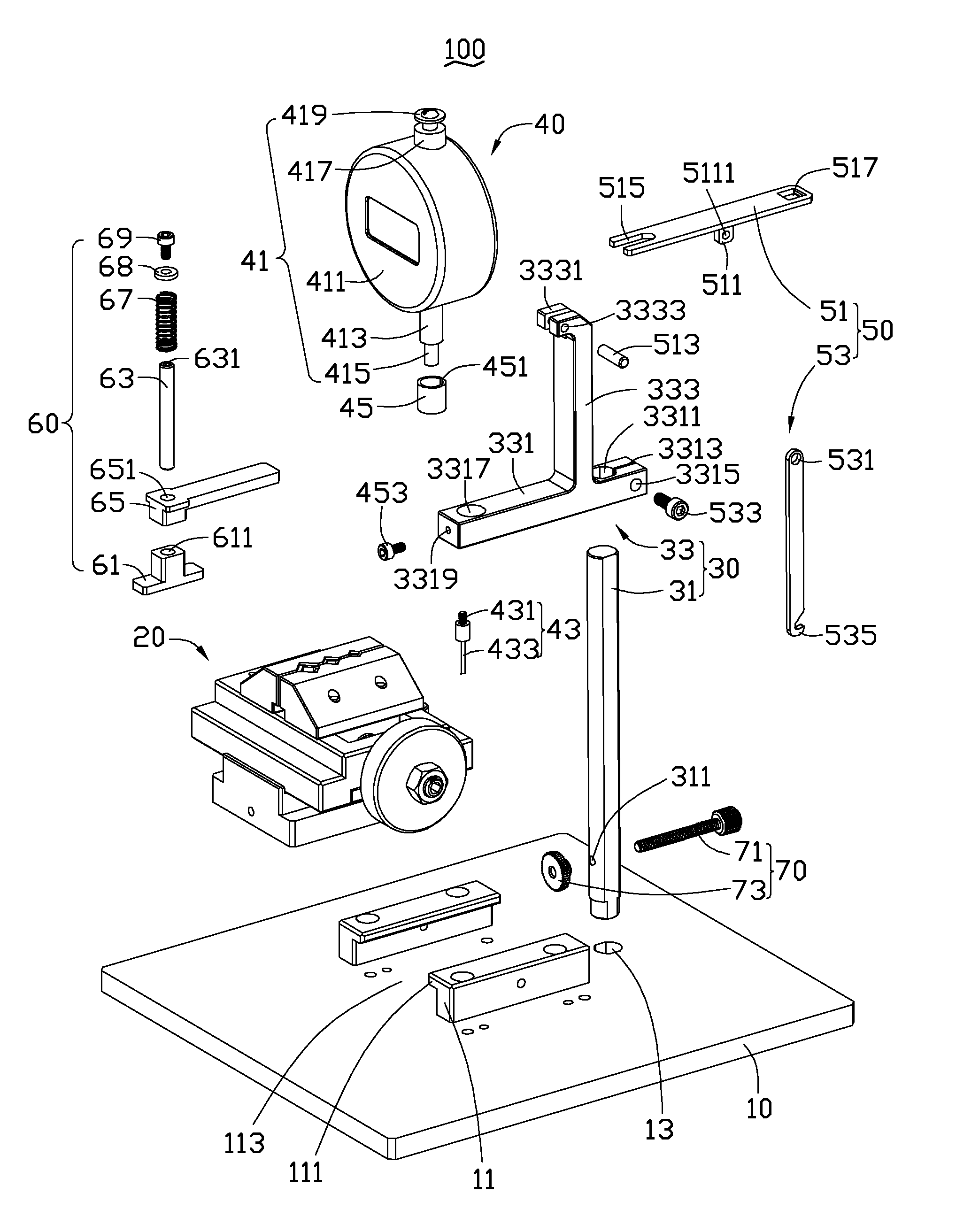
[0013]FIG. 1 shows a depth testing device 100 for testing depths of screw drives. The depth testing device 100 includes a base 10, a supporting assembly 20, a holding assembly 30, a testing assembly 40, a catching assembly 50, and a calibrating assembly 60.

[0014]The base 10 includes two guiding blocks 11 which face and are in parallel to each other. The end of each guiding block 11 far from the base 10 protrudes to define a resisting block 111 towards the other guiding block 11. The guiding blocks 11, the resisting blocks 111, and the base 10 cooperate to form a guiding drive 113. The base 10 further defines a guiding through hole 13.

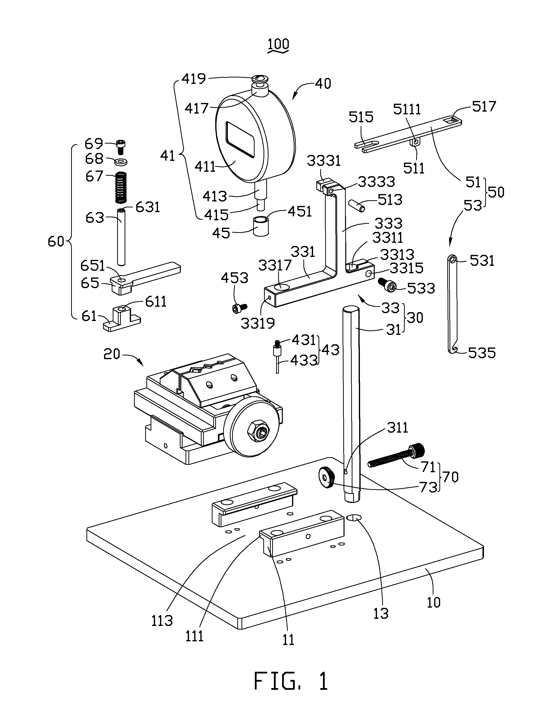
[0015]The supporting assembly 20 is slidably mounted in the guiding drive 113 (see FIGS. 4 and 5). Also referring to FIG. 2, the supporting assembly 20 includes a sliding element 21, a mounting element 23, two supporting elements 25, and an adjusting module 27.

[0016]The sliding element 21 defines two steps 211 opposite to each other on two sides of the ...


PUM


Abstract

A depth testing device for testing depth of a screw drive includes a supporting assembly which is for supporting the screw, a calibrating assembly, and a testing assembly. The calibrating assembly includes a calibrating element which presses on the top end of the screw. The testing assembly includes a testing device and a testing probe, the testing device includes a testing member and a testing pole stretching relative to the testing member. One end of the testing probe is received in the testing pole. The reading of the testing member is reset to zero first, then the other end of the testing probe is moved and is inserted into the drive of the screw, recording the reading of the testing member. The depth of the drive of the screw is calculated by the test reading subtracted by the thickness of the calibrating element.

Description

BACKGROUND[0001]1. Technical Field[0002]The present disclosure generally relates to a depth testing device, especially to a depth testing device for testing depths of screw drives.[0003]2. Description of Related Art[0004]Slotted screws are widely used to connect different elements. The drive formed in the screw should have a certain depth to assure the fastening strength of the elements.[0005]The known method to test the depth of the drive usually uses calipers (when the volume of the screw is large). However, testing using calipers may not produce precise results. When the volume of the screw is small, a cutting-projecting method may be used to test the depth of the drive. However, since the screw is small, it is difficult to assure the cutting precision of the screw, thereby the test results are not precise either. Furthermore, cutting the screw is tedious work.[0006]Therefore, there is room for improvement within the art.BRIEF DESCRIPTION OF THE DRAWINGS[0007]Many aspects of the ...

Claims


Application Information

Patent Timeline
Patent Type & Authority Applications(United States)
IPC IPC(8): G01B5/18
CPCG01B5/18G01B3/28
Inventor ZHANG, BING-JUN
Owner FULIAN PRECISION ELECTRONICS (TIANJIN) CO LTD
Why Eureka
Try Eureka