Air-conditioned seat for a cabin of a vehicle

a technology for air-conditioning seats and cabins, which is applied in the field of air-conditioning seats for cabins of vehicles, can solve the problems of not being comfortable at temperature or humidity levels, parts of the operator's body that come into contact with the seats, and the kind of air-conditioning system is often not sufficient to ensure the well-being of the operator, etc., and achieves the effect of easy and economical production

Inactive Publication Date: 2013-11-14
WEBASTO THERMO & COMFORT ITAL
View PDF27 Cites 25 Cited by
  • Summary
  • Abstract
  • Description
  • Claims
  • Application Information

AI Technical Summary

Benefits of technology

[0007]The purpose of the present invention is to provide an air-conditioned seat and relative air-conditioning system for the cabin of a vehicle, which overcome the drawbacks described above and, at the same time, are easy and economical to produce.

Problems solved by technology

However, this kind of air-conditioning system is often not sufficient to guarantee the well-being of the operator in view of the extreme environmental conditions in which the vehicle is used, and particularly during hot weather due to the huge amount of heat generated by the powerful engine with which such vehicles are normally equipped.
The result is that the parts of the operator's body that come into contact with the seat, which is often very basic for obvious reasons of simplicity and convenience, are never at comfortable temperature or humidity levels.
In other words, despite the presence of the air-conditioning system, the operator feels cold in winter and hot in summer.
Some of these solutions involve complex systems for distributing the conditioned air, which draw in conditioned air from the vehicle's air-conditioning system and distribute this to breathable seating and backrest portions of the seat.
The solutions described above for an air-conditioned seat are, however, not suitable for the cabin of a vehicle, in that they are too complex, and thus expensive and not robust, nor do they provide adequate air-conditioning for the extreme environmental conditions in which the vehicle is normally used.

Method used


Image

  • Air-conditioned seat for a cabin of a vehicle
  • Air-conditioned seat for a cabin of a vehicle
  • Air-conditioned seat for a cabin of a vehicle

Examples


Embodiment Construction

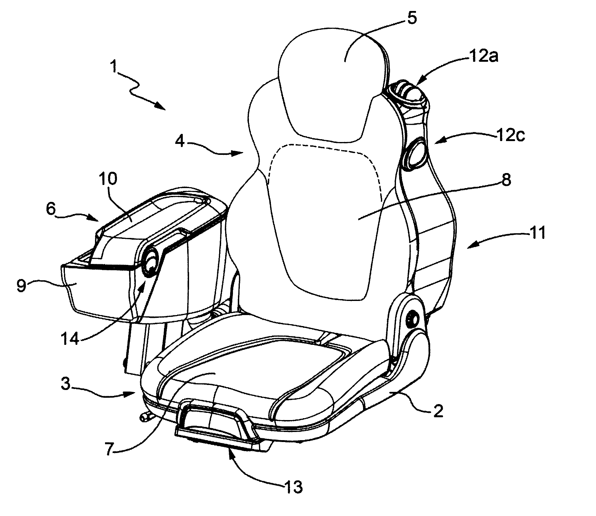
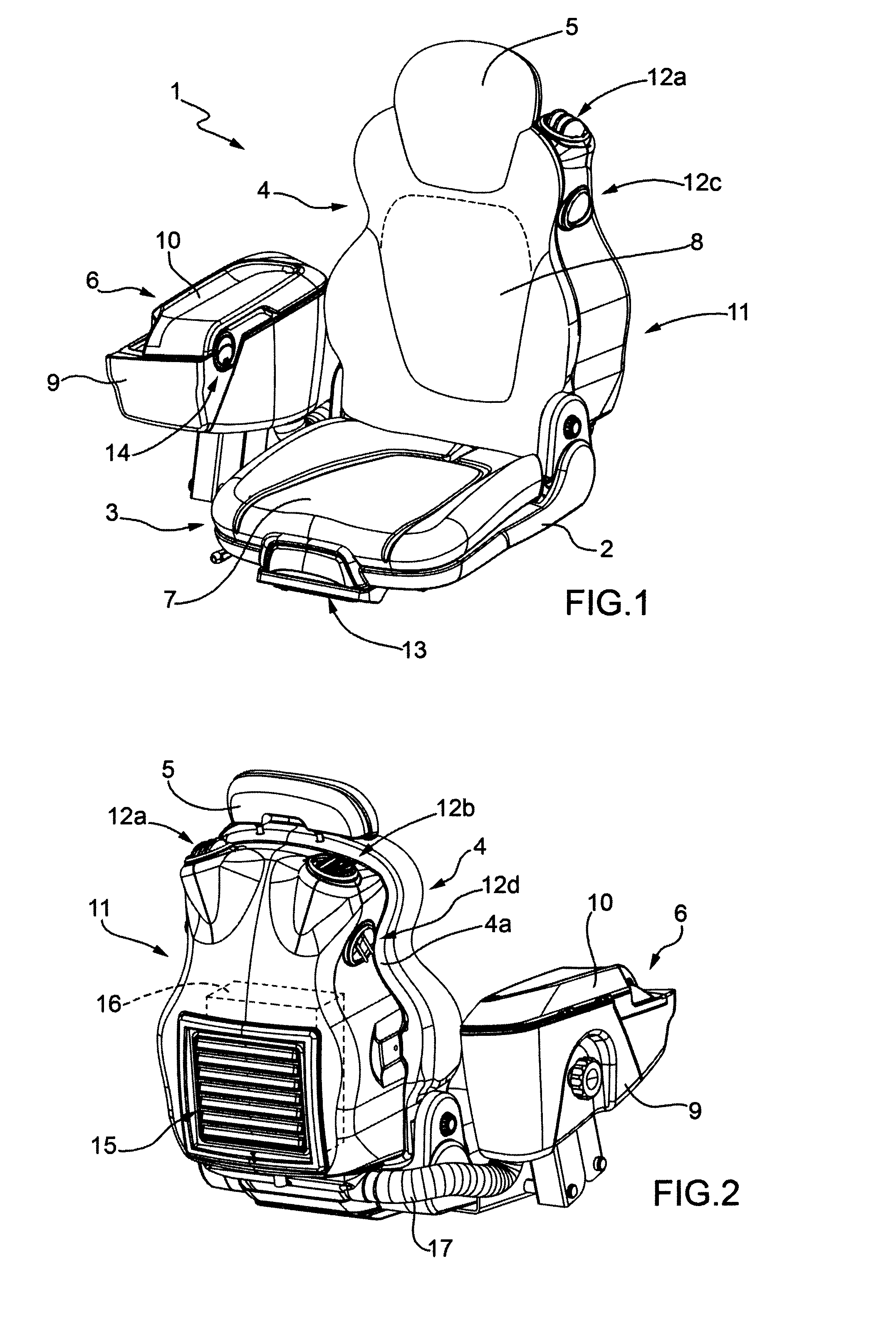
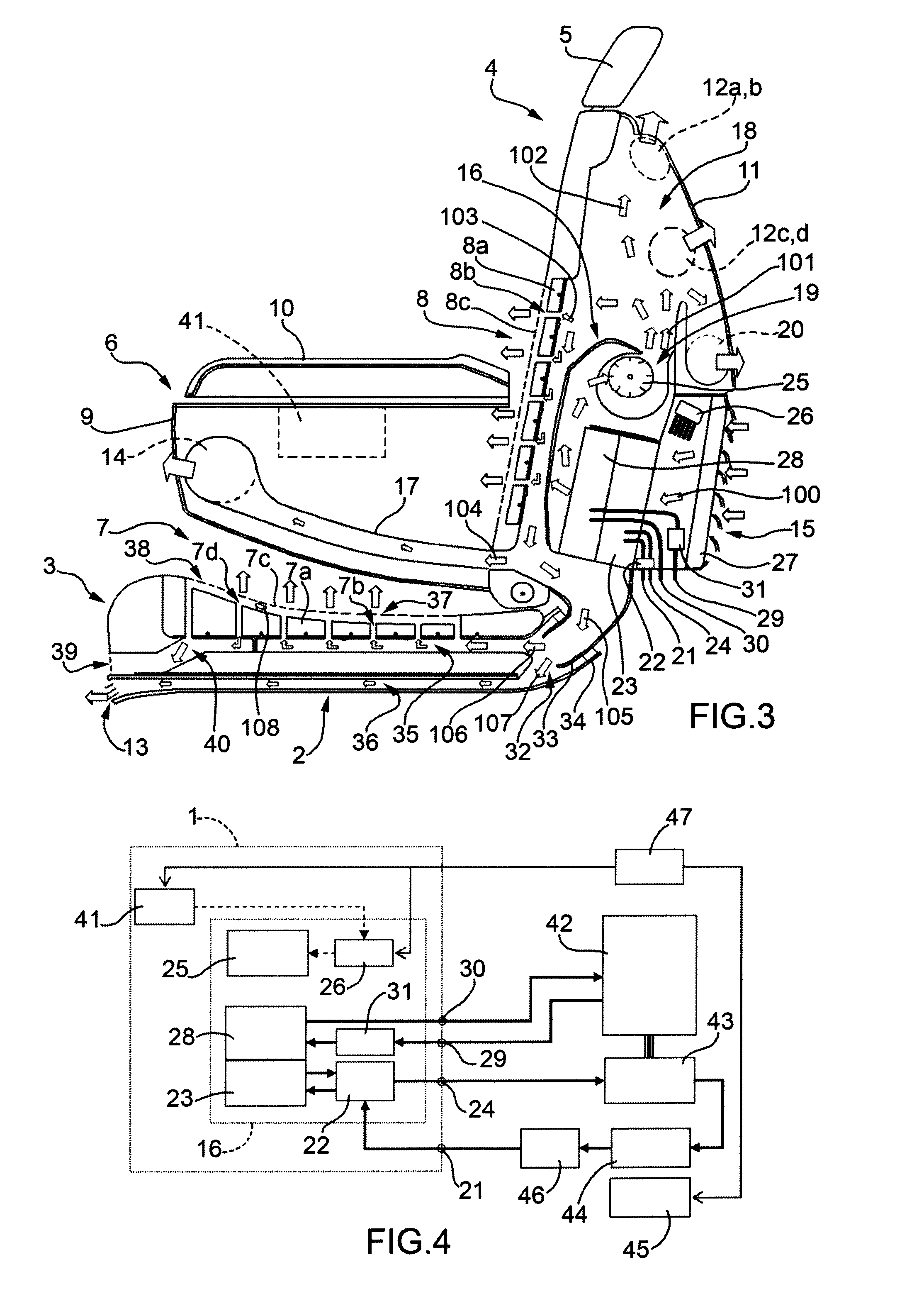
[0014]In FIG. 1, number 1 generally indicates, as a whole, the air-conditioned seat according to the invention and which can be installed in the cabin of a vehicle. The seat 1 comprises a base 2, a seating part 3 mounted on the base 2 and a backrest part 4 hinged to the base 2. The backrest part 4 is provided with a headrest 5. Moreover, the seat comprises a lateral armrest 6 anchored to the base 2. The seating part 3 and the backrest part 4 comprise respective breathable portions 7 and 8, hereinafter, for the sake of simplicity, referred to as breathable seating part portion 7 and breathable backrest part portion 8, which, in use, come into contact with the relative parts of the driver's body (not illustrated). The armrest 6 comprises a substantially hollow element 9 that is open at the top and a cover 10 hinged to the element 9 to close the latter.

[0015]The seat 1 comprises a shell 11 that is rigidly coupled to the rear side 4a (FIG. 2) of the backrest part 4 and provided with one...


PUM


Abstract

A seat for a cabin of a vehicle, presenting breathable seating and backrest portions (7, 8). The seat (1) has a shell (11), which is rigidly coupled to the rear side (4al) of the backrest (4) and presents an air intake (15) and air vents (12a-12d) for the cabin, and an air-conditioning unit (16), which is housed in the shell (11) and has a coolant inlet (21), an expansion valve (22) connected to the coolant inlet (21), an evaporator (23) connected to the expansion valve (22) for cooling the air sucked in, a coolant outlet (24) connected to the expansion valve (22) and an electric fan (25). In the shell (11) and in the base (2) of the seat (1) there are air distribution chambers (18, 32) communicating with the outlet (19) of the air-conditioning unit (16), the air vents (12a-12d) and the breathable seating and backrest part portions (7, 8).

Description

TECHNICAL FIELD[0001]The present invention relates to an air-conditioned seat for a cabin of a vehicle.[0002]In particular, the present invention is advantageously, but not exclusively, intended for use in medium and small-sized cabins typical of work vehicles such as, for example, tractors, mini-excavators, crane trucks, telescopic handlers, skid steer loaders, etc., to which the following description specifically refers but without any loss of generality.BACKGROUND ART[0003]The most modern cabins for the types of vehicles listed above are hermetically sealed and air-conditioned for improved comfort of the operator sitting inside the cabin. Such vehicles are normally provided with a conventional air-conditioning system comprising a compressor, a condenser, an expansion valve and an evaporator connected in series and in that order by means of ducts through which a coolant flows to form a coolant refrigeration circuit. The compressor is normally driven by the engine of the vehicle. T...

Claims


Application Information

Patent Timeline
Patent Type & Authority Applications(United States)
IPC IPC(8): B60N2/56
CPCB60N2/56B60H1/00207B60H1/00285B60H2001/00228B60N2/5635B60N2/5657
Inventor BERGAMINI, DIMITRI
Owner WEBASTO THERMO & COMFORT ITAL
Why Eureka
Try Eureka