System for managing runoff water

Inactive Publication Date: 2013-11-14
DRAKE SUSANNAH
View PDF8 Cites 9 Cited by
  • Summary
  • Abstract
  • Description
  • Claims
  • Application Information

AI Technical Summary

Benefits of technology

[0004]Disclosed in this specification is a system for reducing runoff from an urban area into a body of water. In one embodiment, water flows from a sedimentation basin and into plurality of bioretention cells, each extended at an angle relative to the sedimentation basin. Overflow water flows from the plurality of biorention cells into an elongated filter. In another embodiment, a system for reducing run off from an elevated road is disclosed. The system includes an enclosure with a sedimentation basin and a biofiltration basin.
[0005]In a first exemplary embodiment, a system for reducing runoff from an urban area into a body of water is disclosed. This system includes several elongated bioretention cells, each fluidly connected to an elongated sedimentation basin and fluidly connected to at least one adjacent elongated bioretention cell. The elo

Problems solved by technology

Ultimately, these emissions are introduced into a ne

Method used


Image

  • System for managing runoff water
  • System for managing runoff water
  • System for managing runoff water

Examples


Embodiment Construction

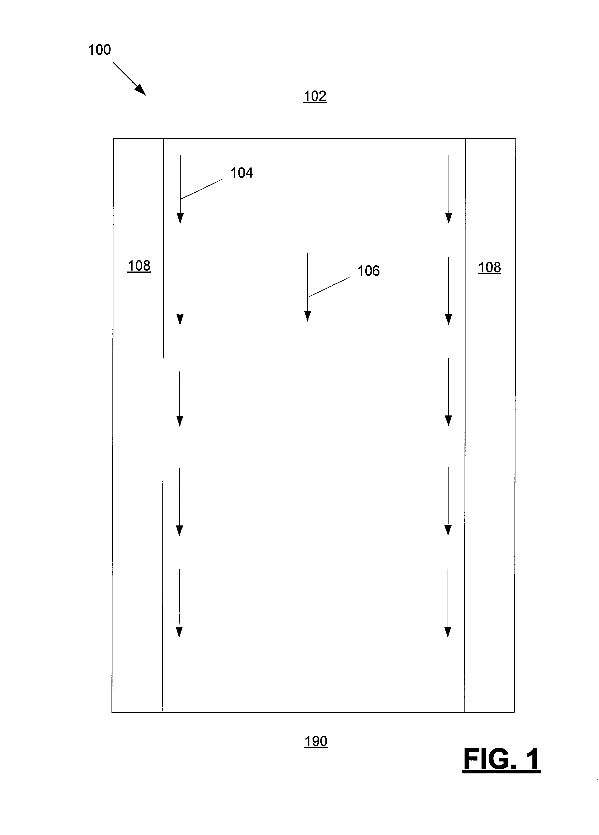
[0018]Referring to FIG. 1, an exemplary system 100 for managing water is depicted from an aerial perspective. Water flows from an urban area 102 following a water path 104 in a first direction 106. In the embodiment depicted, the water path 104 substantially follows raised areas 108 (e.g. a curb of a street or walkway). The water path 104 carries with it street runoff (e.g. debris and pollutants including petrochemicals, lead and cadmium) from urban area 102. In system 100, this street runoff is conveyed to a body of water 190 (e.g. a pond, lake, river or ocean). Additionally, during times of increased rainfall, the entire system 100 may become flooded. Due to the flooding, the street runoff can accumulate is inappropriate locations (e.g. above the raised areas 108). The effects of the runoff can render the landscape covered by system 100 unsuitable for pedestrians. An improved system is therefore desired.

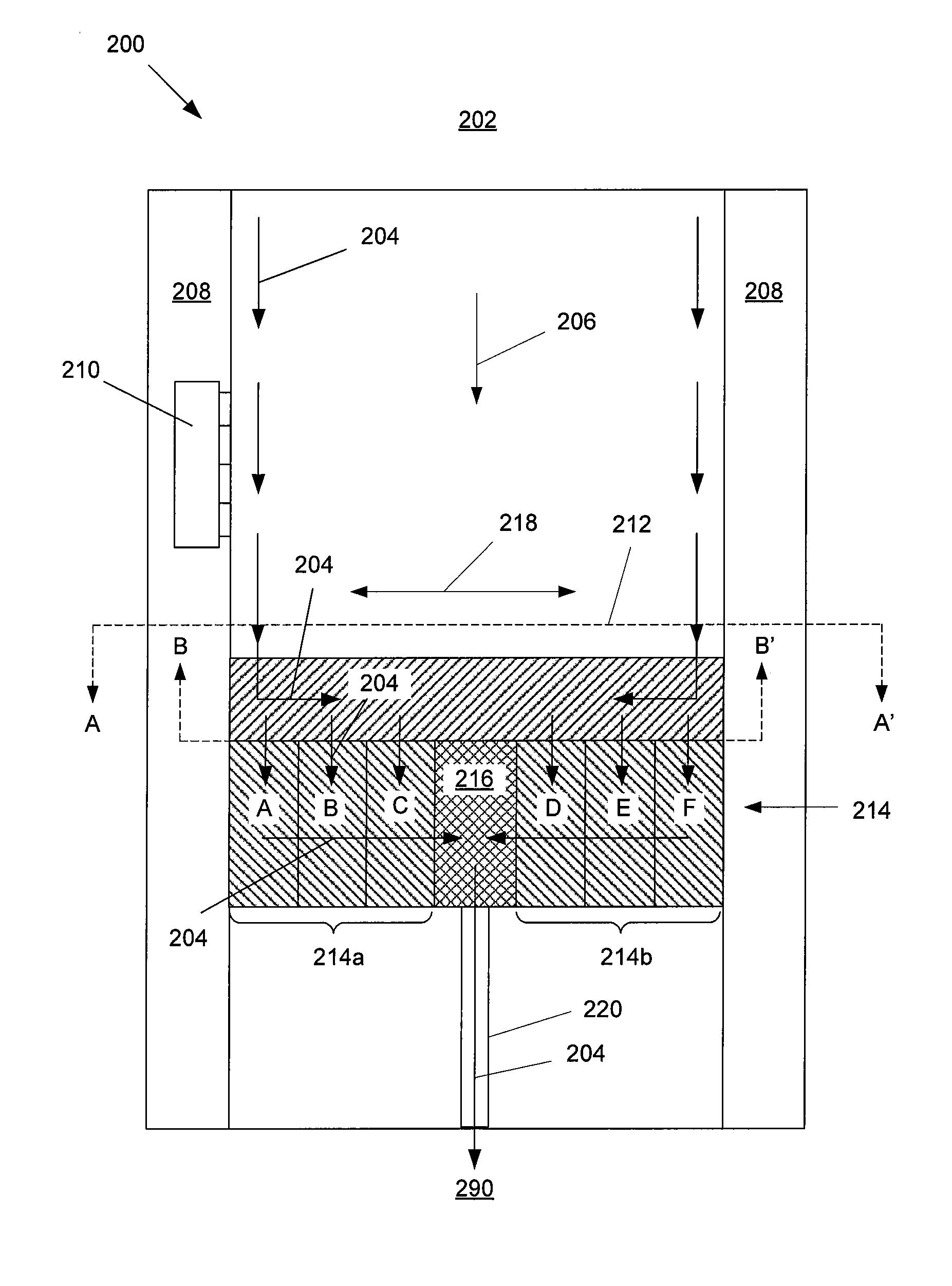
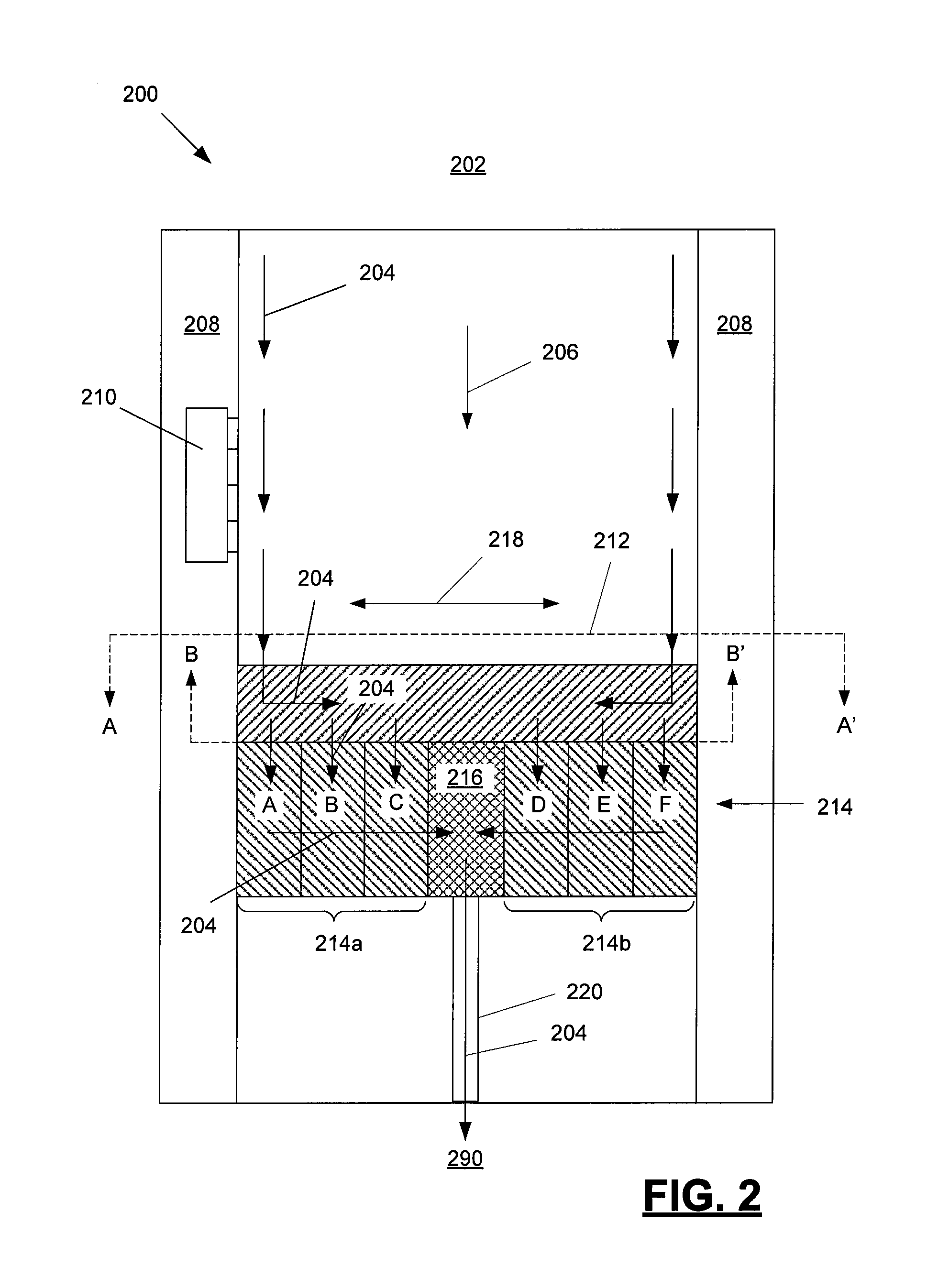
[0019]Referring to FIG. 2, an exemplary system 200 for reducing runoff from an...


PUM


Abstract

Disclosed in this specification is a system for reducing runoff from an urban area into a body of water. In one embodiment, water flows from a sedimentation basin and into plurality of bioretention cells, each extended at an angle relative to the sedimentation basin. Overflow water flows from the plurality of biorention cells into an elongated filter. In another embodiment, a system for reducing run off from an elevated road is disclosed. The system includes an enclosure with a sedimentation basin and a biofiltration basin.

Description

CROSS-REFERENCE TO RELATED APPLICATIONS [0001]This application claims priority to and the benefit of U.S. provisional patent application Ser. No. 61 / 685,676 (filed Mar. 22, 2012) which application is incorporated herein by reference in its entirety.FIELD OF THE INVENTION [0002]This invention relates, in one embodiment, to a system for managing water from an urban area, including runoff water from a road.BACKGROUND [0003]As combustion vehicles are operated, a wide variety of emissions are produced. Some of these emissions accumulate on the surface of roads. During a subsequent rainstorm, these emissions are washed into a nearby drain. Ultimately, these emissions are introduced into a nearby body of water, thereby contaminating the water. An improved method of managing runoff water is desired.SUMMARY OF THE INVENTION [0004]Disclosed in this specification is a system for reducing runoff from an urban area into a body of water. In one embodiment, water flows from a sedimentation basin a...

Claims


Application Information

Patent Timeline
IPC IPC(8): E03F1/00
CPCE03F1/001C02F3/327C02F2103/001C02F2101/32C02F2101/20Y02W10/10
Inventor DRAKE, SUSANNAH
Owner DRAKE SUSANNAH
Why Eureka
Try Eureka