Method for coordinated transmission in a plurality of cells of a wireless communication system

a wireless communication system and cell technology, applied in the field can solve the problems of limiting the spectrum efficiency increasing the complexity of wireless communication systems, and requiring coordination between cells, so as to maximize the diversity order or the degree of spatial multiplexing, maximize the effect of transmitting antennas and minimizing interferen

Active Publication Date: 2013-11-14
TELECOM ITALIA SPA
View PDF10 Cites 46 Cited by
  • Summary
  • Abstract
  • Description
  • Claims
  • Application Information

AI Technical Summary

Benefits of technology

[0021]This approach has the advantage that operating at scheduling level (L2) it is possible to maximally exploit the transmitting antennas in order to maximize the diversity order or the degree of spatial multiplexing towards the useful radio link. Conversely when the interference rejection is carried out at physical layer level (L1) the antennas are simultaneously used to transmit over the useful radio link and to minimize the interference towards an interfered UE located in an adjacent cell. In this case then it is not possible to maximize the diversity order or the degree of spatial multiplexing towards the useful radio link.
[0022]In another aspect of the invention, measures carried out by the user equipment to detect an interference condition, are provided on the whole transmission band, i.e. on the whole range of frequency which can be transmitted by the access apparatuses. By implementing this type of measures UE gets a good knowledge of the interference situation over the whole transmission band and therefore can provide the network with information useful for improving scheduling.
[0023]In a further aspect of the invention, the network provides the user equipment with information on the specific frequency ranges wherein quality measures shall be performed. In particular these frequency ranges are frequency ranges that are currently allocated or that are to be allocated to the user by the serving cell. This provides the advantage of reducing power consumption of the user equipment.

Problems solved by technology

Inter-cell interference is one of the main factors that limit spectrum efficiency of wireless communication systems, in particular for users located at the cell edge of a cellular system.
Coordination between cells has clearly a cost represented by the overhead deriving from the exchange of information (data, control and measurements) over the radio interface and over the backhauling links between the cooperating cells.
This has the drawback of increasing UE complexity (as more hardware for processing and storing is needed) and of stressing battery consumption (as several measurements are required).

Method used


Image

  • Method for coordinated transmission in a plurality of cells of a wireless communication system
  • Method for coordinated transmission in a plurality of cells of a wireless communication system
  • Method for coordinated transmission in a plurality of cells of a wireless communication system

Examples


first embodiment

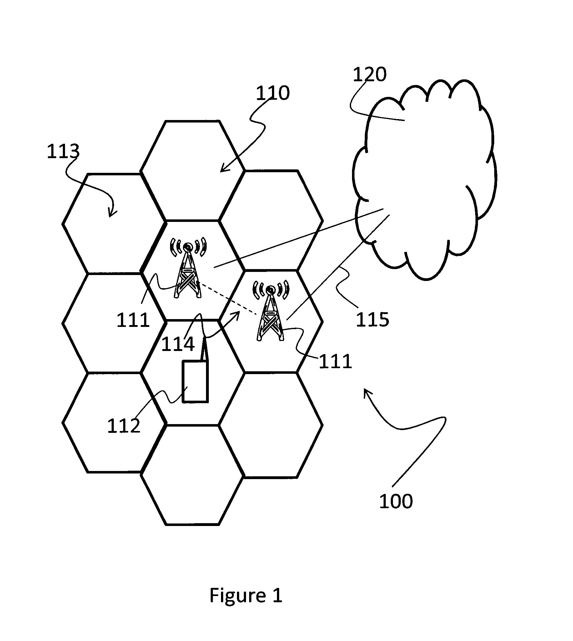
[0074]In a first embodiment, UE 112 explicitly reports the CSI. In case of an explicit CSI reporting, a quantized version of the channel matrix Hcellj→UEi of the radio link between the interfering cell Ij and UE 112 is estimated and reported by UE 112 to the serving cell. This information is then conveyed (step 213) through the backhauling (i.e. the X2 interface) to the interfering cell.

[0075]The interfering cell Ij exploits the channel knowledge over the interfering link in order to reduce interference experienced by UE 112 (step 214). In particular, interfering cell Ij computes suitable precoding weights according to the multi-cell coordination scheme implemented in the network. For example in case of a pure multi-cell interference rejection scheme the precoding weights are calculated at the interfering cell Ij in order to place a null in the radiation diagram over the relevant direction towards UE 112. Example of algorithms suitable for this purpose are those based on the concept...

second embodiment

[0076]In a second embodiment, UE 112 reports an indicator correlated to the CSI; in this case UE implicitly reports the CSI. In case of implicit reporting, the CSI is preferably quantized by means of a codebook and the reported quantity is represented by an index, denoted as PMI (Precoding Matrix Index), of the best element to be picked up in the codebook. The implicit reporting reduces the CSI overhead at the price of a lower accuracy with respect to the explicit CSI reporting. Also in case of codebook based precoding the PMI selection done by the UE depends on the type of coordination scheme that is implemented in the network. In case of a pure interference rejection scheme the PMI is selected in order to minimize the power leakage between the interfering cell Ij and UE 112. In this case the useful data are transmitted to UE 112 only by the serving cell. In case of a joint transmission scheme the PMI is selected in order to maximize the channel gain between the interfering cell Ij...

third embodiment

[0088]In a third embodiment the value of the threshold Δi(k) is related to the load of the uplink radio interface where the CoMP signalling is transmitted. In general a lower value of the threshold is configured as the uplink load increases. In this respect it is also possible to imagine a centralized algorithm in the base station that jointly controls the value of the threshold as a function of the uplink load for all the users served by the cells which are under the control of the eNodeB. For example the algorithm may start to decrease the threshold as the uplink load increases by defining for each user a priority level related to the QoS class and the service type.


PUM


Abstract

A method for coordinated transmission in a plurality of cells of a wireless communication system, wherein a user equipment triggers coordinate transmission of a plurality of cells if it detects an interference condition between signals received by the plurality of cells, the user equipment detecting the interference condition based on a radio quality metric dynamically set by the network and triggering coordinate transmission by transmitting a trigger signal to at least a cell of the plurality of cells. A radio equipment and a user equipment for use in a wireless communication system can implement coordinated transmission with the method.

Description

TECHNICAL FIELD[0001]The present invention relates to the field of wireless communication systems and more particularly to multicell coordinated multipoint transmission and reception (CoMP) systems and methods.[0002]In detail, the invention finds preferred application in advanced wireless communication systems like LTE-A (Long Term Evolution-Advanced), wherein use of coordinated transmission techniques are under discussion and evaluation in 3GPP (Third Generation Partnership Project) group. However, the invention is not only limited to wireless communication systems based on OFDM (Orthogonal Frequency Division Multiplexing) like LTE, LTE-A, WiMAX (Worldwide Interoperability for Microwave Access), UMB (Ultra-Mobile Broadband) but it is also applicable in systems that use different radio access techniques like for example CDMA (Code Division Multiple Access).[0003]The invention also relates to equipment for use in such wireless communication systems.BACKGROUND ART[0004]Inter-cell inte...

Claims


Application Information

Patent Timeline
Patent Type & Authority Applications(United States)
IPC IPC(8): H04W24/02
CPCH04W24/02H04B1/1027H04B7/022H04W24/10H04W72/12H04W28/04H04W24/00
Inventor CARETTI, MARCOD'AMICO, VALERIAMELIS, BRUNOSABELLA, DARIO
Owner TELECOM ITALIA SPA
Why Eureka
Try Eureka