Display-Based Control for Motor Grader

a display-based control and motor grader technology, applied in mechanical machines/dredgers, analogue processes for specific applications, instruments, etc., can solve problems such as blade-obstacle collisions, incomplete grading, and complex tasks of motor grader users

Inactive Publication Date: 2013-11-14
CATERPILLAR INC
View PDF15 Cites 32 Cited by
  • Summary
  • Abstract
  • Description
  • Claims
  • Application Information

AI Technical Summary

Benefits of technology

[0011]In accordance with yet another aspect of the disclosure, a system is provided for controlling a motor grader during grading near a curb, the motor grader having a blade for grading an underlying surface. The system includes a display for displaying to an operator of the motor grader an image showing a gap between the blade and the curb and for receiving user input to alter the gap to a target distance. A controller is configured to adjust a position of the blade during grading of the underlying surface to maintain the gap between the blade and the curb at the target distance.

Problems solved by technology

Given the ability to control the blade position, frame articulation, and wheel steering, the operation of a motor grader presents users with a complex task.
Failure to properly control any one of these variables in such circumstances can result in blade-obstacle collisions or incomplete grading.
While the system of Coats et al. does assist operators by automating certain machine positioning tasks, it does not address blade positioning for sensitive operations such as cul-de-sac grading and contouring.

Method used


Image

  • Display-Based Control for Motor Grader
  • Display-Based Control for Motor Grader
  • Display-Based Control for Motor Grader

Examples


Embodiment Construction

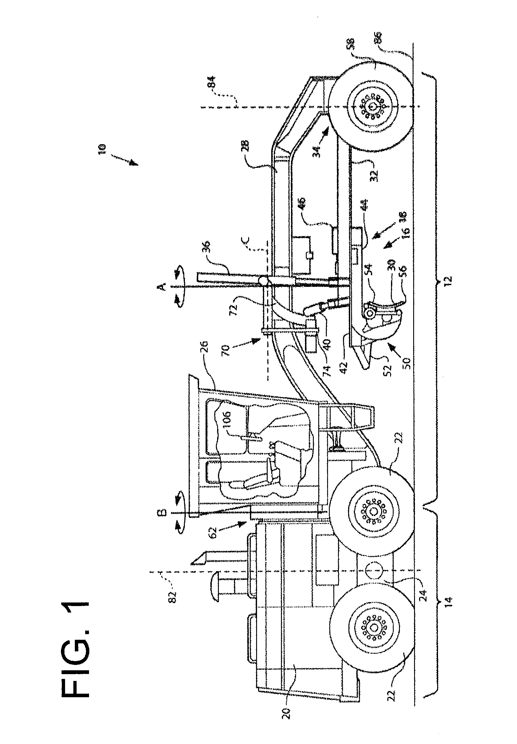
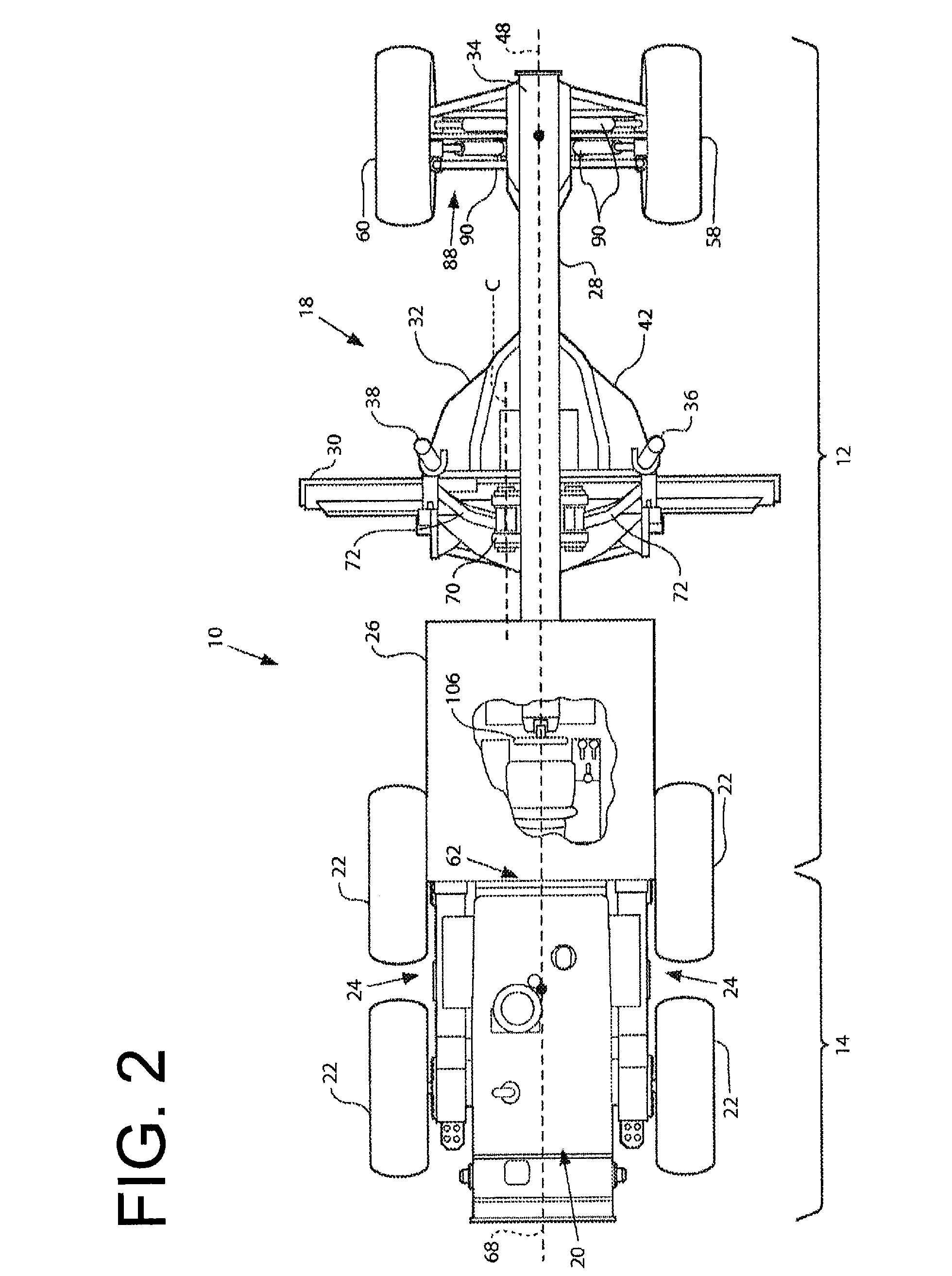
[0023]The present disclosure provides a system and method for motor grader steering and blade control for operations relative to roadway markers such as, but not limited to, curbs and the like. Referring now to FIG. 1 and FIG. 2, there is shown an exemplary motor grader in accordance with one embodiment of the present disclosure. The illustrated motor grader 10 includes a front frame 12, rear frame 14, and a work implement 16. In the context of a motor grader, the work implement 16 is typically a blade assembly 18, also sometimes referred to as a drawbar-circle-moldboard assembly (DCM). The blade assembly 18 may include a separate blade portion and a moldboard portion, and such arrangements will be referred to herein collectively as the blade, moldboard, or DCM.

[0024]The rear frame 14 includes a power source, not shown, contained within a rear compartment 20. The power source is typically operatively coupled through a transmission, not shown, to rear traction devices or wheels 22 fo...


PUM


Abstract

A method, controller and system in accordance with various aspects of the present disclosure provide display-based control of a motor grader for grading near a curb or other roadway marker. A blade image is displayed to the operator on a display screen showing a portion of the blade and a portion of the curb or marker, and input is received from the operator to move the blade such that a gap between the portion of the blade and the portion of the curb conforms to a target distance. The gap between the portion of the blade and the portion of the curb is monitored as the motor grader moves along the curb and the location of the blade relative to the curb is automatically adjusted such that the gap remains at the target distance. The blade image may be updated as the motor grader proceeds along the curb.

Description

TECHNICAL FIELD OF THE DISCLOSURE[0001]The present disclosure relates to motor grader operation and, more particularly, relates to motor grader blade and steering control for operations near roadway markers such as curbs.BACKGROUND OF THE DISCLOSURE[0002]Motor graders are earth-moving machines that are employed in a variety of tasks, including as shaping tools to create banks, ditches, and berms, as surface preparation tools for scarification and other surface treatments, and as finishing tools to refine construction site and roadway surfaces to final shape and contour. Although not universally applicable, motor graders typically include a front frame and a rear frame that are joined at an articulation joint. The rear frame includes compartments for housing the power source and cooling components, the power source being operatively coupled to the rear wheels for primary propulsion of the machine. The rear wheels are typically arranged in tandem sets on opposing sides of the rear fra...

Claims


Application Information

Patent Timeline
Patent Type & Authority Applications(United States)
IPC IPC(8): E02F3/84
CPCE02F3/844E02F3/764E02F3/7645E02F3/765E02F3/7659E02F3/842E02F3/847E02F9/262
Inventor BRAUNSTEIN, MICHAELZHU, YONGLIANG
Owner CATERPILLAR INC
Why Eureka
Try Eureka