Wind Power Generation Equipment

a technology of wind power generation and equipment, applied in the direction of electric generator control, machines/engines, mechanical equipment, etc., can solve the problems of insufficient and incessant energy resources, limited application of existing wind power generators, etc., to improve connection reliability, reduce the effect of start-up wind speed and reinforce the reliable mounting of stators

Inactive Publication Date: 2013-11-21
ZHEJIANG LINIX MOTOR
View PDF1 Cites 3 Cited by
  • Summary
  • Abstract
  • Description
  • Claims
  • Application Information

AI Technical Summary

Benefits of technology

[0004]The technical purpose of the invention is mainly solved by the following technical solution. Wind power generation equipment is provided, comprising a support bar. An annular hood, with a stator assembly mounted and fixed therein, is fixed on the support bar. The stator assembly comprises an annular stator mounting plate which is fixed with an inner stator ring and an outer stator ring distributed concentrically. The inner stator ring is formed of multiple inner stators distributed uniformly at interval in the peripheral direction, and the outer stator ring is formed of multiple outer stators distributed uniformly in the peripheral direction. An annular track is formed between the inner stator ring and the outer stator ring. A rotor assembly and the stator assembly are coaxially and pivotally connected on the support bar, and the rotor assembly is formed of a rotor holder and multiple rotors distributed uniformly on the periphery of the rotor holder at interval. The rotor holder is formed of an outer ring and an inner ring, multiple blade fixing members of a spoke structure are arranged between the outer ring and the inner ring of the holder, and blades are fixed on the blade fixing members. The rotors are protruded and fixed on the outer ring of the holder axially, and a steel magnet of the rotors is located in the annular track between the inner stator ring and the outer stator ring. In the invention, the rotors are directly fixed on the outer ring of the holder, in this way, the steel magnet and the blades may rotate synchronously, thus the wind power generation equipment may be started by an extremely low wind speed, as low as 0.2 m / s, such wind power generation equipment has very broad application scope and may be applied to the families. In addition, in the invention, multiple inner stators form an inner stator ring and multiple outer stators form an outer stator ring, and an annular track is formed between the inner stator ring and the outer stator ring to allow the rotors to run, in this way, wind energy driving the blades to rotate may be fully transformed into electric energy, and the transformation efficiency is high.
[0012]So, the invention has the characteristics of low start-up wind speed and small limitation in the applications.

Problems solved by technology

Wind resource is a kind of inexhaustible and incessant energy resource.
However, torque is generally transmitted between blades and rotors of the existing wind generators by rotating shafts or gear mechanisms, a high wind speed of typically 3.5 m / s is often required to start up the existing wind power generators, and the application of the existing wind power generators is limited largely.

Method used


Image

  • Wind Power Generation Equipment
  • Wind Power Generation Equipment
  • Wind Power Generation Equipment

Examples


embodiment 1

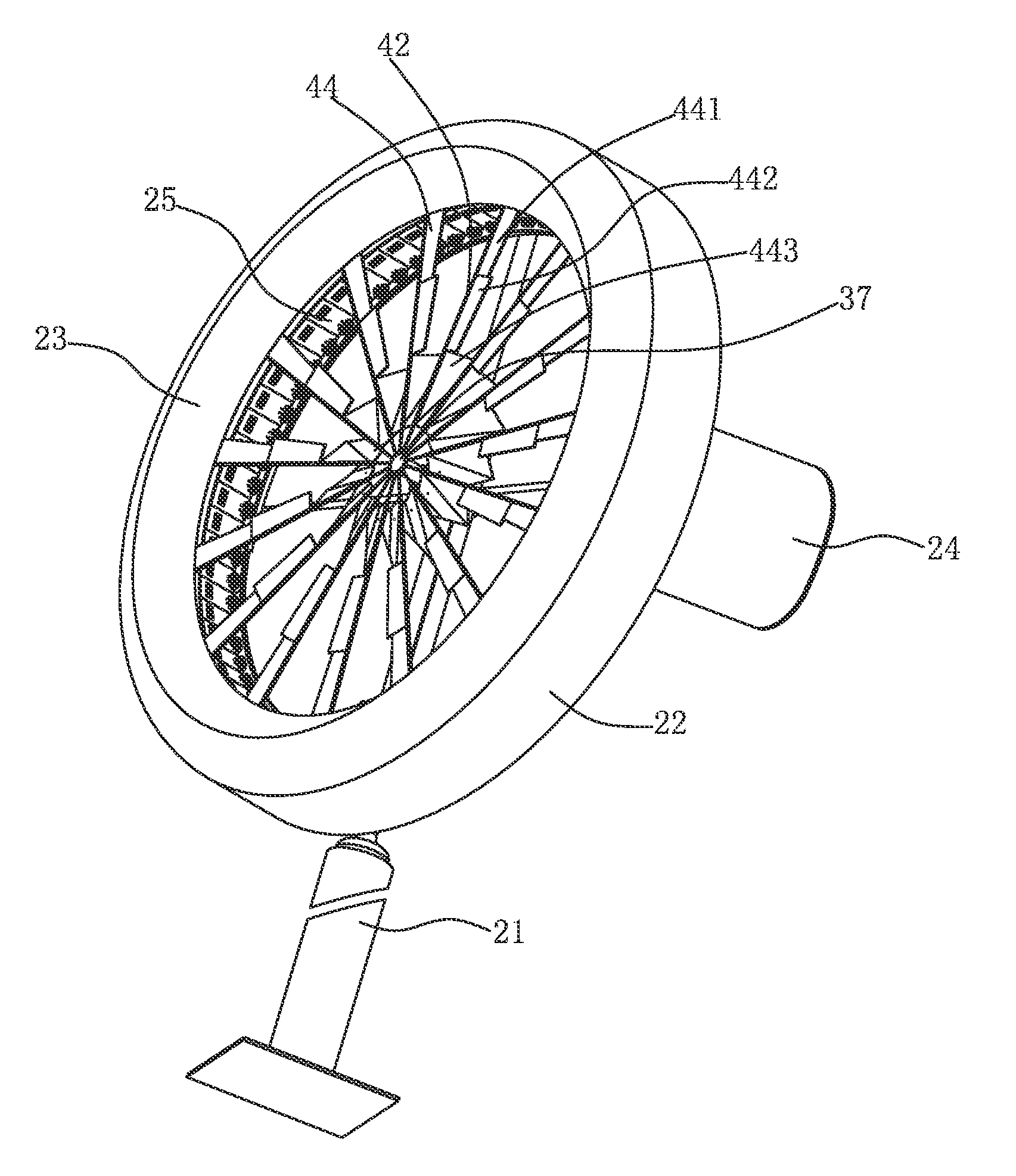
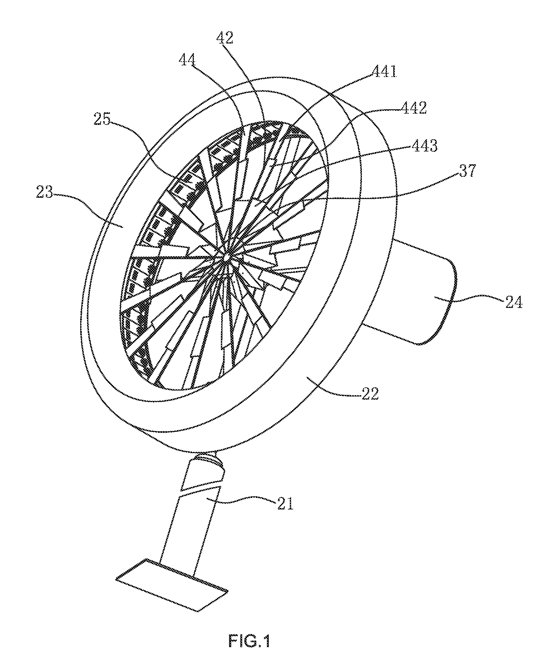
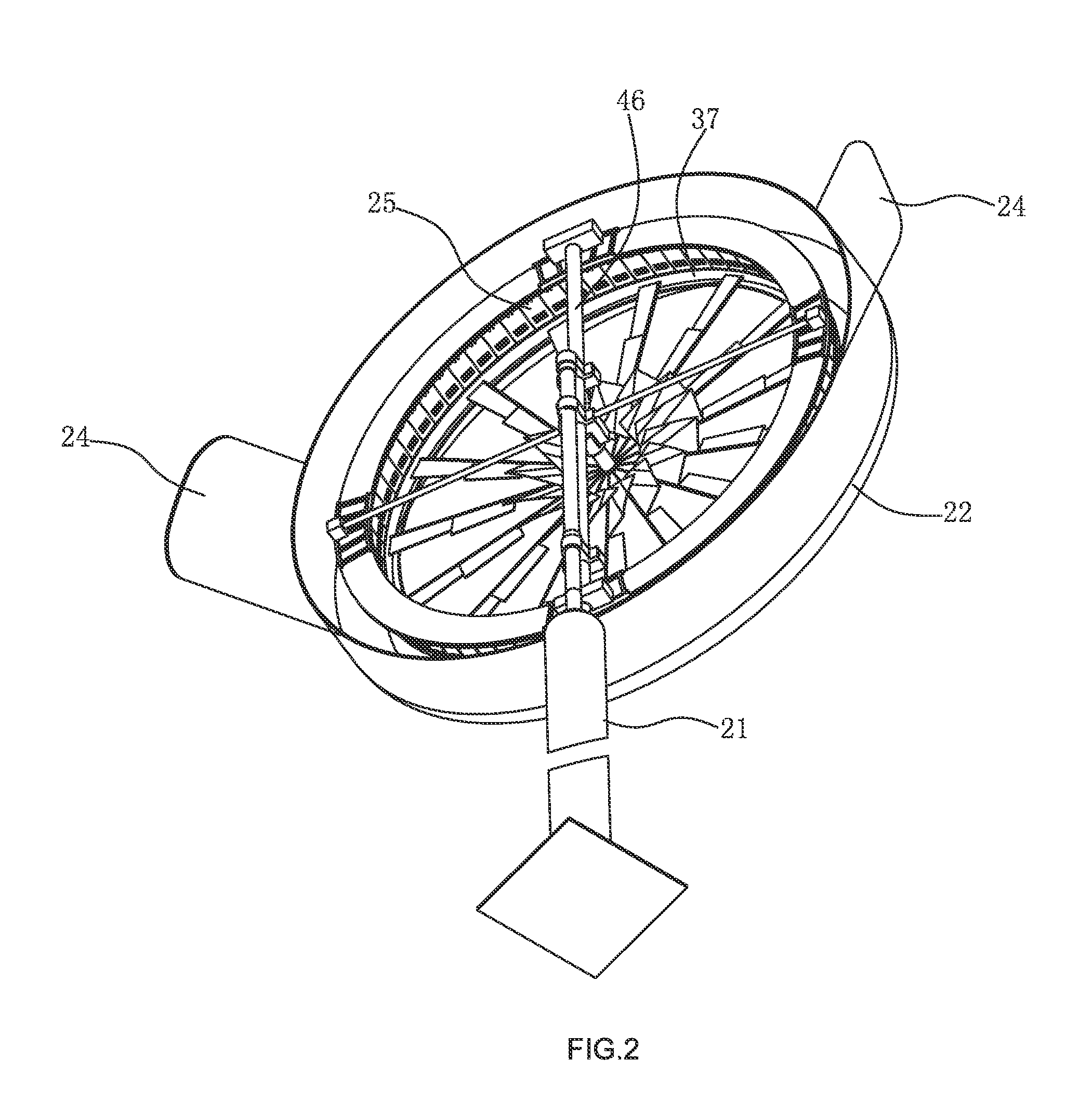
[0023]As shown in FIGS. 1, 2, 3 and 4, an annular hood 22 is fixed on a support bar 21. A front end of the annular hood 22 is formed into an annular frustum surface 23, and a rear end edge of the annular hood 22 is provided with two tail fins 24 distributed symmetrically on left and right sides. The tail fins 24 extend backward and outward from the edge of the annular hood 22, and the cross section of the tail fins 24 is an arc. A stator assembly 25 is mounted and fixed in the annular hood 22. As shown in FIG. 5, the stator assembly 25 comprises an annular stator mounting plate 26. A crossed support frame 46 is fixed on an upper end of the support bar 21, and a rear end face of the annular stator mounting plate 26 is fixed with the crossed support frame. The annular stator mounting plate 26 is fixed with an inner stator ring 27 and an outer stator ring 28 distributed concentrically. The inner stator ring 27 is formed of sixty eight inner stators 29 distributed uniformly at interval ...


PUM


Abstract

An annular hood, with a stator assembly mounted and fixed therein, is fixed on the support bar. The stator assembly comprises an annular stator mounting plate which is fixed with an inner stator ring and an outer stator ring distributed concentrically. An annular track is formed between the inner stator ring and the outer stator ring. A rotor assembly and the stator assembly are coaxially and pivotally connected on the support bar, and the rotor assembly is formed of a rotor holder and multiple rotors distributed uniformly on the periphery of the rotor holder at interval. The rotor holder is formed of an outer ring and an inner ring, multiple blade fixing members of a spoke structure are arranged between the outer ring and the inner ring of the holder, and blades are fixed on the blade fixing members. The rotors are protruded and fixed on the outer ring of the holder axially, and a steel magnet of the rotors is located in the annular track between the inner stator ring and the outer stator ring.

Description

TECHNICAL FIELD OF THE INVENTION[0001]The invention relates to wind power generation equipment, belonging to the technical field of wind power generation equipment manufacture.BACKGROUND OF THE INVENTION[0002]Wind resource is a kind of inexhaustible and incessant energy resource. The utilization of wind in power generation may reduce environmental pollution and save conventional energy resources such as coal and oil. The wind power generation technology is mature, with relatively low cost among renewable energy resources and broad prospect for development. The wind power generation technology may be applied flexibly. It can operate not only on-grid collaboratively but also off-grid independently, and it may also form complementary power generation systems with other energy technologies. However, torque is generally transmitted between blades and rotors of the existing wind generators by rotating shafts or gear mechanisms, a high wind speed of typically 3.5 m / s is often required to s...

Claims


Application Information

Patent Timeline
Patent Type & Authority Applications(United States)
IPC IPC(8): F03D9/00
CPCF03D9/002F05B2220/706F03D9/25F03D13/20F03D15/20H02K7/183H02K21/14H02K21/22H02K2201/15Y02E10/72Y02E10/728
Inventor SUN, ZHUBIN
Owner ZHEJIANG LINIX MOTOR
Why Eureka
Try Eureka