Vehicle Warning Light System

a technology for warning lights and vehicles, applied in the direction of curtain suspension devices, building scaffolds, domestic objects, etc., can solve the problems of difficult positioning on the handlebars, bulky housing,

Inactive Publication Date: 2013-11-21
RANSOM STEVEN ANDREW
View PDF6 Cites 32 Cited by
  • Summary
  • Abstract
  • Description
  • Claims
  • Application Information

AI Technical Summary

Problems solved by technology

The housing is bulky and difficult to site on the handlebars in a position which the rider can operate without moving their hand from the handgrips.
Therefore, this indicator light system can be distracting for the rider to use, just as they are about to make a maneuver, and is potentially dangerous.

Method used


Image

  • Vehicle Warning Light System
  • Vehicle Warning Light System
  • Vehicle Warning Light System

Examples


Embodiment Construction

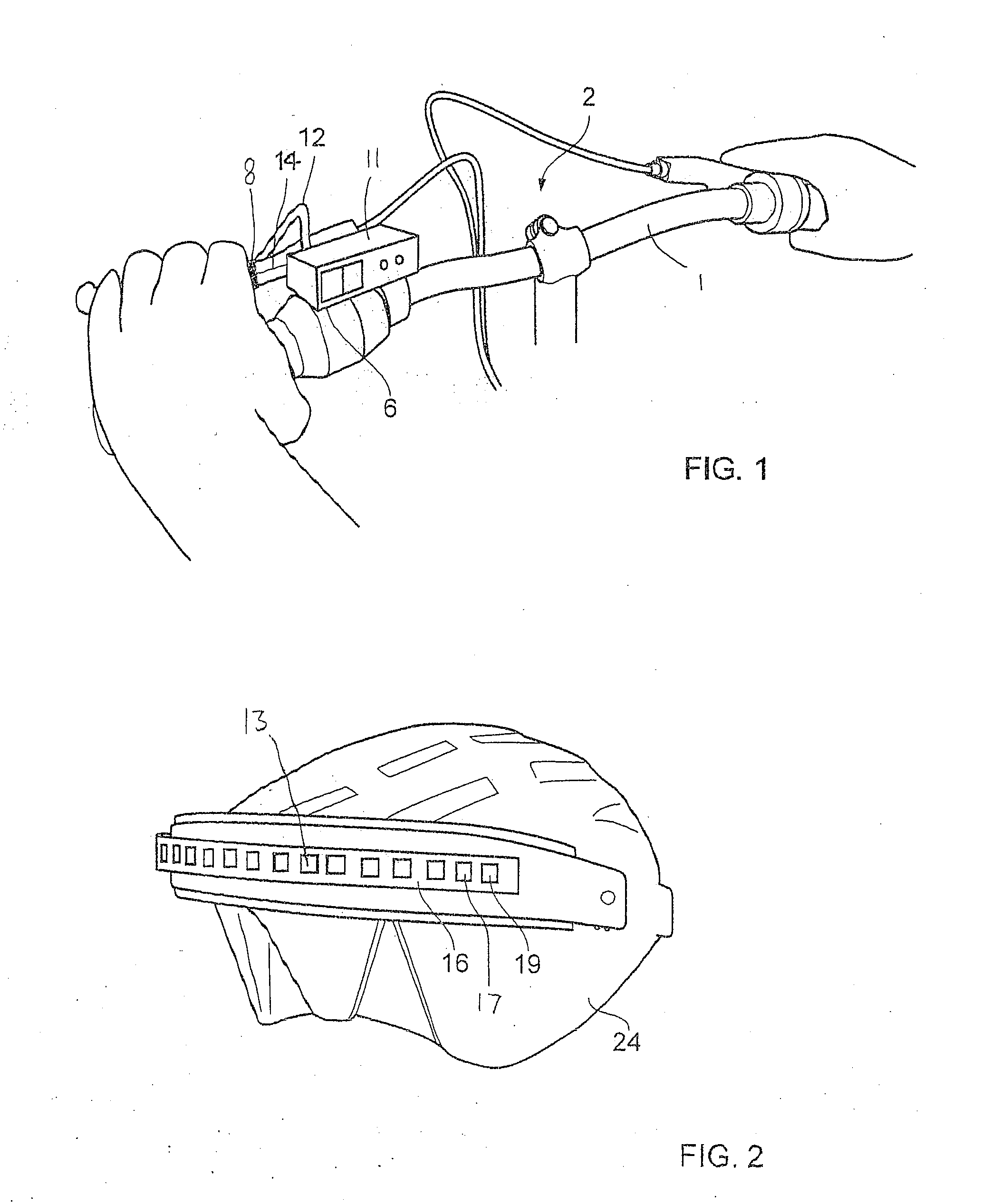
[0032]This invention has application to any vehicle which might benefit from the provision of indicator lights, such as direction indicator lights and brake warning indicator lights. However, for simplicity in the detailed description below, the invention is described in relation to a brake and direction indicator light system for a bicycle 2.

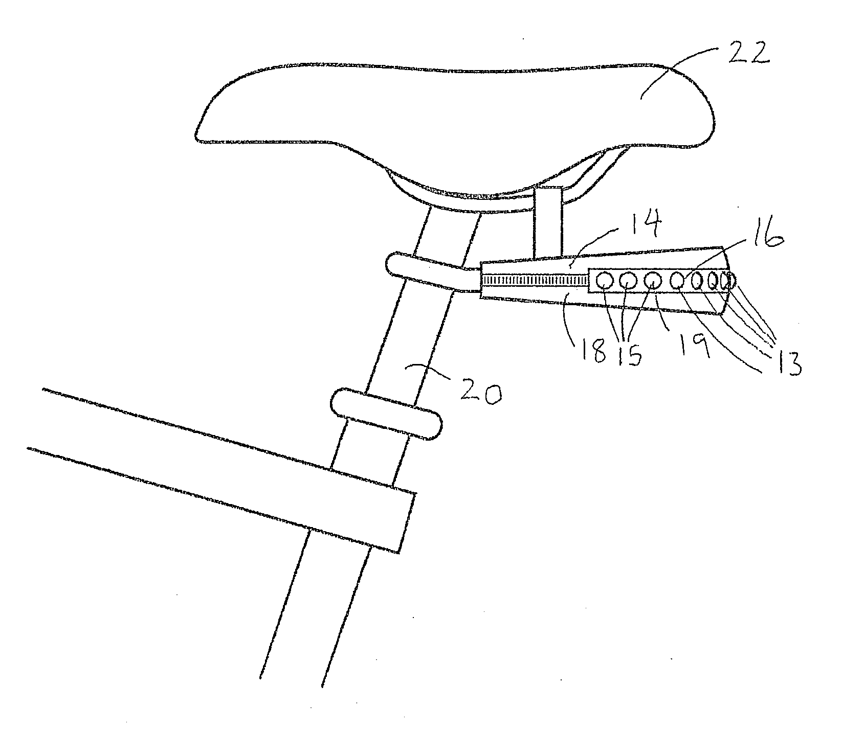
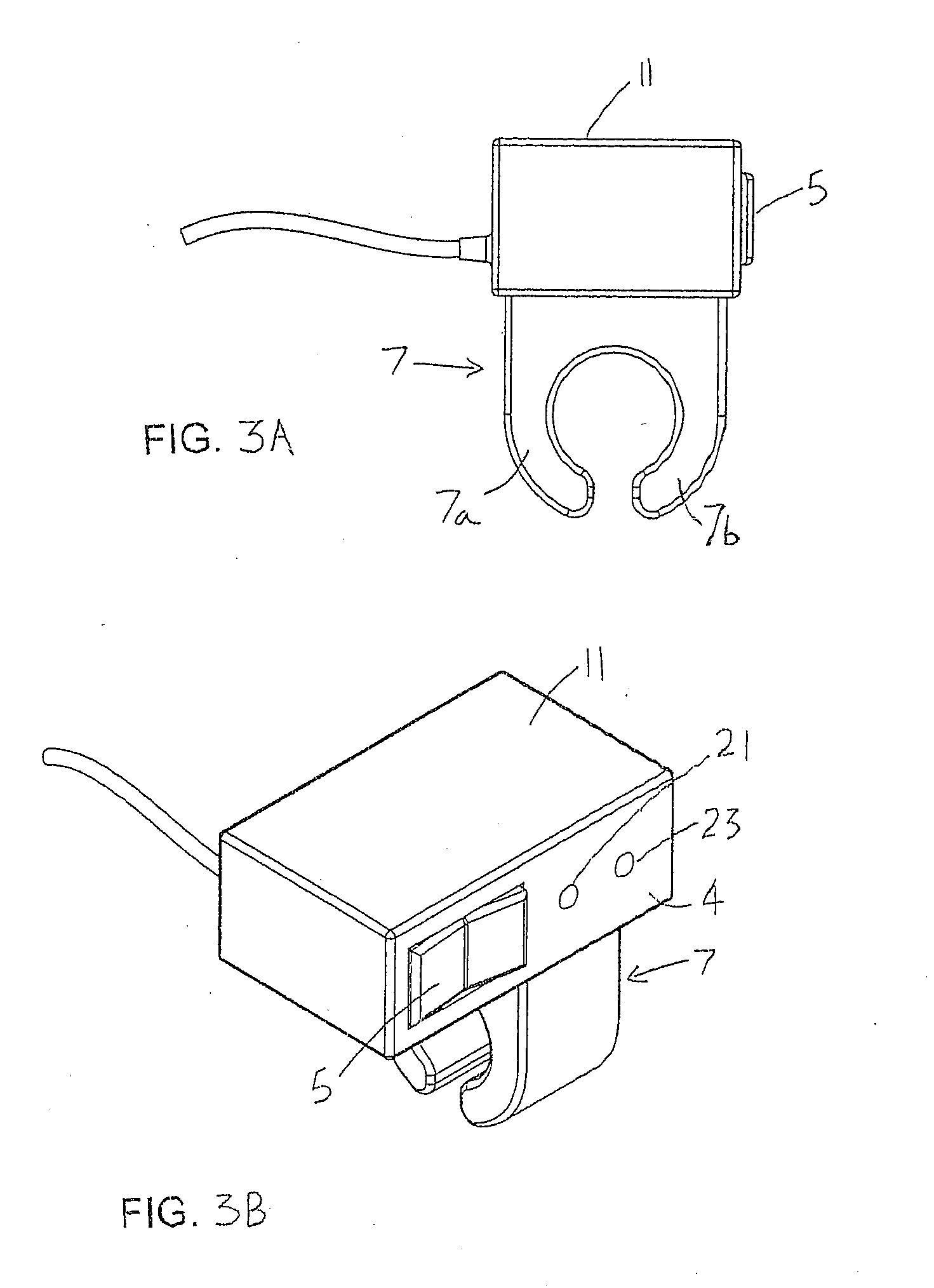
[0033]Referring to Figs. to 1 and 2, a bicycle indicator light system includes a bicycle mounted kit comprising a direction indicator and brake light control unit 6 mounted in a housing 11 and connected to a brake indicator switch 8 by means of a flexible electric cable 12. A wireless sender unit in the housing 11 communicates with a remote wireless receiver unit in a rear mounted lighting arrangement 16.

[0034]The rear mounted lighting arrangement 16 is electrically connected to a brake light / rear light 13 and left and right indicator lights 15, 17. The lights 13, 15, 17 and / or the wireless receiver unit may be fitted in separate housings or ma...


PUM


Abstract

A mount is adapted for attaching a brake switch to a brake control lever of a vehicle, such as a bicycle. The mount and / or the switch may include part of a vehicle lighting system. The vehicle lighting system may include a control unit incorporating a wireless sender unit, which is electrically connected to the switch, a wireless receiver unit, and a turn / direction and / or brake indicator light electrically connected to the wireless receiver unit.

Description

BACKGROUND OF THE INVENTION[0001]This invention relates to vehicle warning light systems which can be retrofitted, or fitted as original equipment, to any vehicle. Particularly, although not exclusively, this invention relates to a wireless bicycle warning light system which can be provided with both direction indication lights and brake indicator lights.[0002]EP 1394029 discloses a bicycle indicator light system comprising a wireless sender unit which is intended for fitment to the handlebar of a bicycle and includes a housing on which are mounted the rider operated indictor light switches. The housing is bulky and difficult to site on the handlebars in a position which the rider can operate without moving their hand from the handgrips. Therefore, this indicator light system can be distracting for the rider to use, just as they are about to make a maneuver, and is potentially dangerous. The present invention was developed to address this problem.SUMMARY OF THE INVENTION[0003]Accord...

Claims


Application Information

Patent Timeline
Patent Type & Authority Applications(United States)
IPC IPC(8): B60Q1/44B62J6/16
CPCB60Q1/44B62J6/16A42B3/0453B62J6/165B62J6/056B62J6/045
Inventor RANSOM, STEVEN ANDREW
Owner RANSOM STEVEN ANDREW
Why Eureka
Try Eureka