
Methods and systems for doppler recognition aided method (DREAM) for source localization and separation

a doppler recognition and source localization technology, applied in the direction of transducer details, electrical transducers, signal processing, etc., can solve the problems of difficult estimation of correlated sources in echoic environments, difficult source localization, and difficult acoustic localization and analysis of multiple industrial sound sources such as motors, pumps

Active Publication Date: 2013-11-21
SIEMENS AG
View PDF5 Cites 11 Cited by
  • Summary
  • Abstract
  • Description
  • Claims
  • Application Information

AI Technical Summary

Benefits of technology

The present invention provides systems and methods for determining the direction of arrival of multiple acoustical sources that are transmitting simultaneously using a linear microphone array with multiple microphones. By measuring the Doppler shift of signals from the microphones, the system can determine the virtual speed of the sources and the direction of the source relative to the microphone array. The invention has applications in areas such as audio and speech processing.

Problems solved by technology

Acoustic localization and analysis of multiple industrial sound sources such as motors, pumps etc., are challenging as their frequency content is largely time invariant and emissions of similar machines are highly correlated.
In Proc. of International Conference on Independent Component Analysis and Signal Separation (ICA2001), pages 651-656, 2001” such as disjoint time-frequency content of the sources, do not hold, and yield unsatisfactory results.
It is, however, difficult to estimate this for correlated sources in echoic environments.
Source localization is very difficult if sources are possibly in the near field of the microphones.
It is challenging to test and account for the presence of these sources.
However, this results in extremely high data-rates and is too computationally expensive

Method used


Image

  • Methods and systems for doppler recognition aided method (DREAM) for source localization and separation
  • Methods and systems for doppler recognition aided method (DREAM) for source localization and separation
  • Methods and systems for doppler recognition aided method (DREAM) for source localization and separation

Examples


Embodiment Construction

[0040]Methods for Doppler recognition aided methods for acoustical source localization and separation and related processor based systems as provided herein in accordance with one or more aspects of the present invention will be identified herein as DREAM or the DREAM or DREAM methods or DREAM systems.

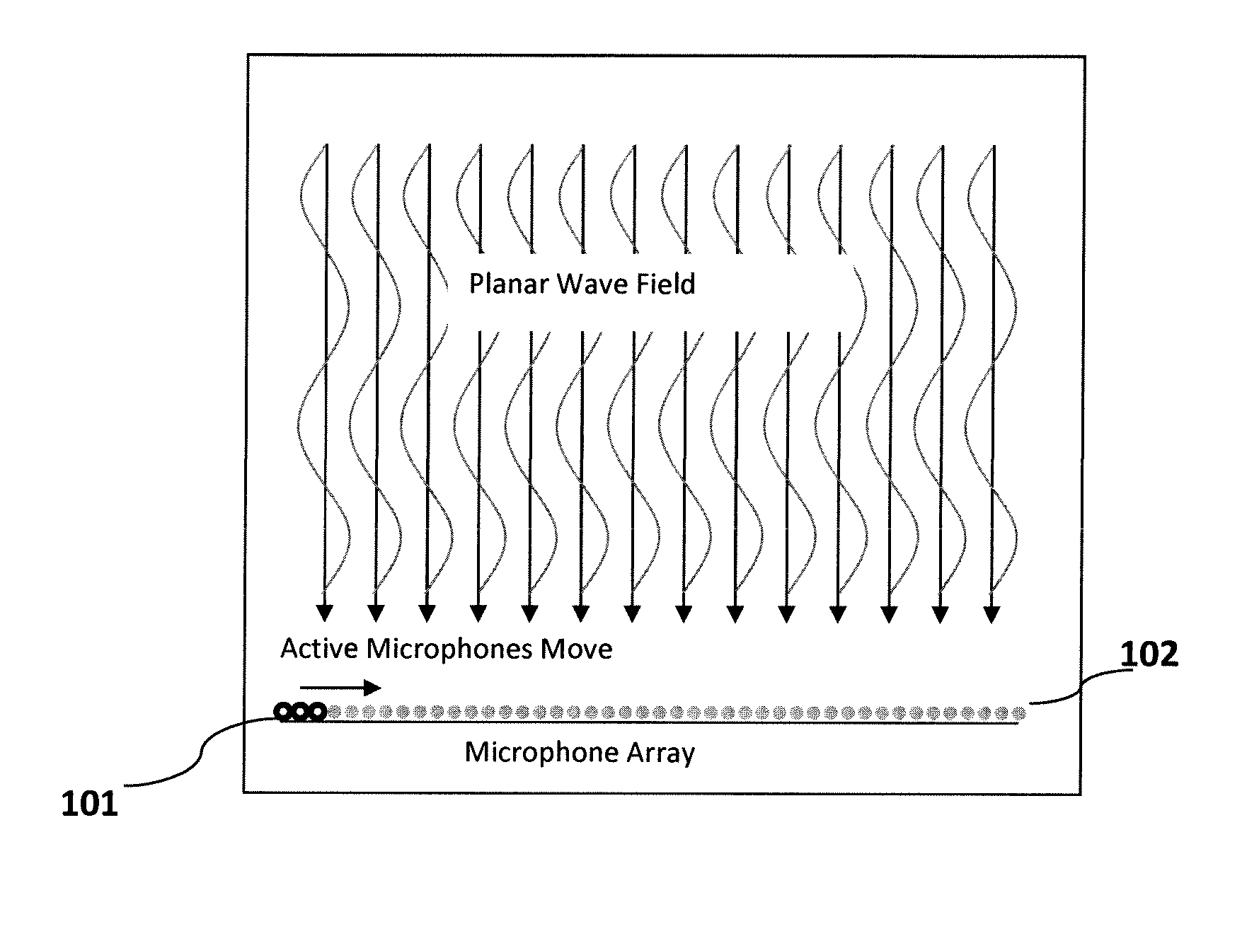
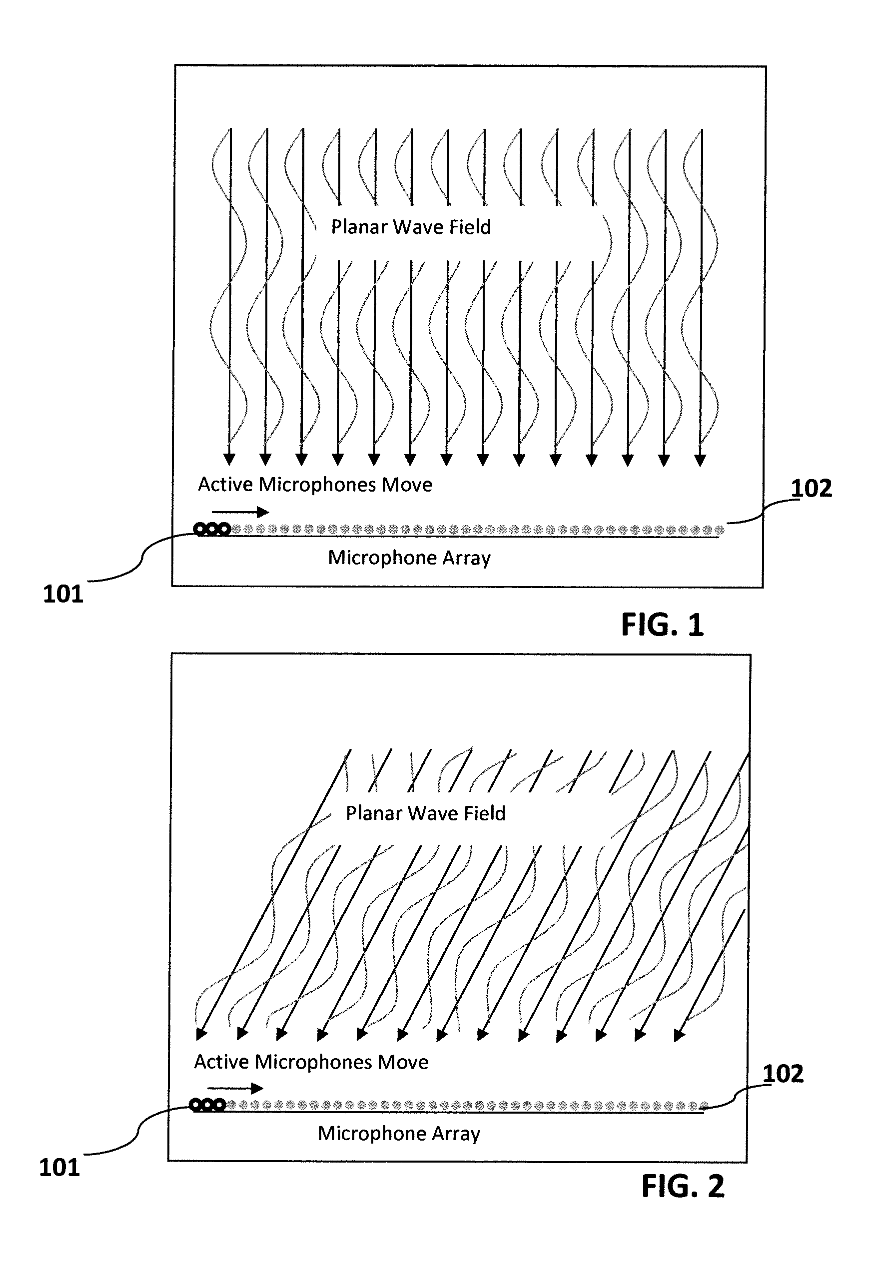
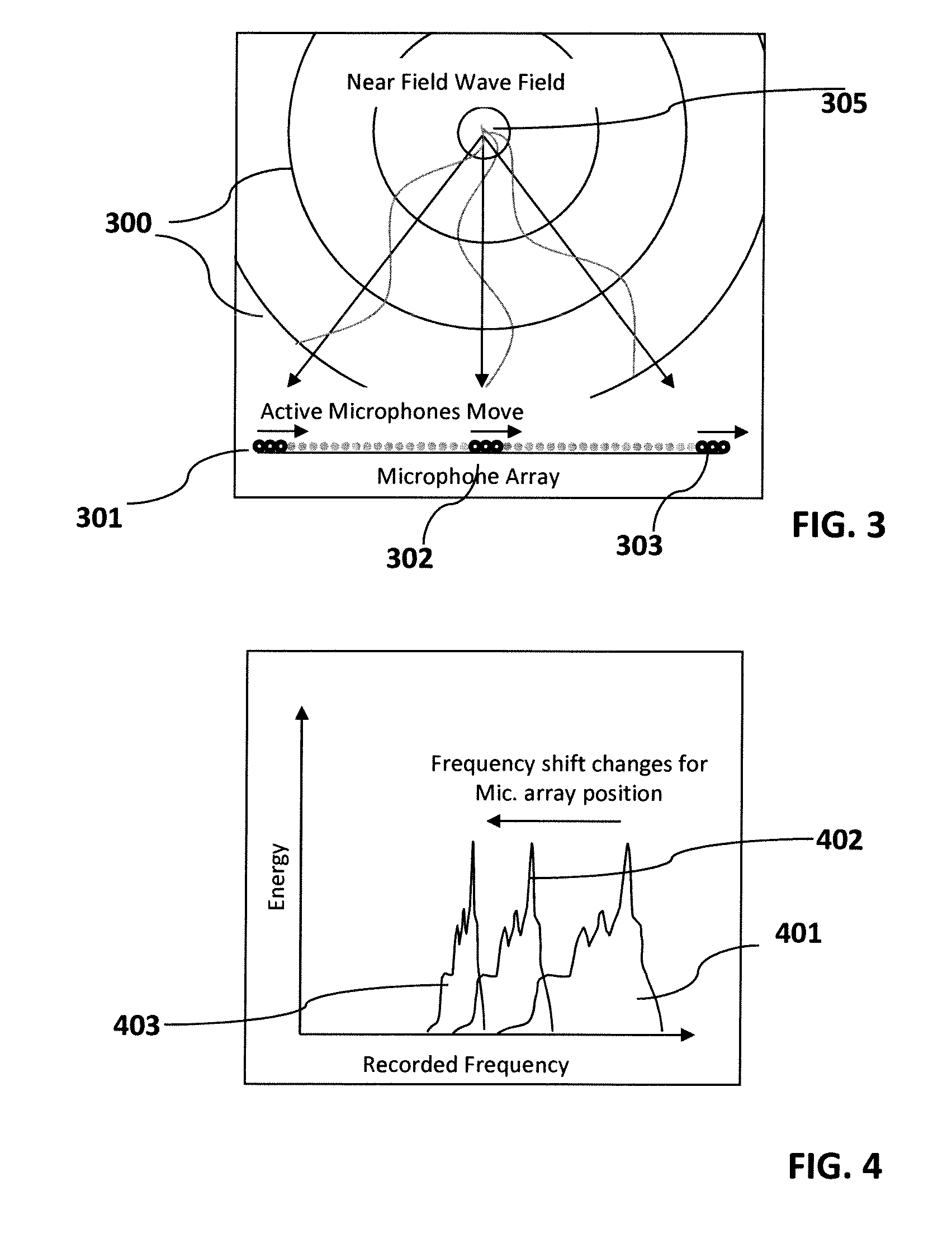
[0041]The DREAM methods and systems for source localization and separation simulate a moving microphone array by sampling different microphones of a large microphone array at consecutive sampling times. An assumption is that sources far away from the array generate planar wave fields. FIGS. 1 and 2 illustrate the concept of a virtually moving microphone array for planar wave fields from sources at different locations.

[0042]The DREAM concept illustrated. FIG. 1 shows that a planar wave field arrives from a source orthogonal to the array. The frequencies recorded by the virtually moving microphone array 101 represent the frequencies of the arriving wave. FIG. 2 shows planar wave field ar...


PUM


Abstract

Systems and methods are provided for source localization and separation by sampling a large scale microphone array asynchronously to simulate a smaller size but moving microphone array. Signals that arrive from different angles at the array are shifted differently in their frequency content. The sources are separated by evaluating correlated and even equal frequency content. Compressive sampling enables the utilization of extremely large scale microphone arrays by reducing the computational effort orders of magnitude in comparison to standard synchronous sampling approaches. Processor based systems to perform the source separation methods are also provided.

Description

BACKGROUND OF THE INVENTION[0001]The present invention relates generally to acoustic source separation and localization and more particularly to acoustic source separation with a microphone array wherein a moving microphone array is simulated.[0002]Acoustic localization and analysis of multiple industrial sound sources such as motors, pumps etc., are challenging as their frequency content is largely time invariant and emissions of similar machines are highly correlated. Therefore, standard assumptions for localization, taken e.g. in DUET as described in “[I] J S. Rickard, R. Balan, and J. Rosca. Real-Time Time-Frequency Based Blind Source Separation. In Proc. of International Conference on Independent Component Analysis and Signal Separation (ICA2001), pages 651-656, 2001” such as disjoint time-frequency content of the sources, do not hold, and yield unsatisfactory results.[0003]More powerful Bayesian DOA methods such as MUST as described in “[2] T. Wiese, H. Claussen, J. Rosca. Par...

Claims


Application Information

Patent Timeline
IPC IPC(8): H04R3/00
CPCH04R3/00H04R1/406H04R3/005H04R2430/20H04R2430/21
Inventor CLAUSSEN, HEIKO
Owner SIEMENS AG
Learn More