Sports face guard

Active Publication Date: 2013-11-28
THE MASURI GRP LTD
View PDF16 Cites 8 Cited by
  • Summary
  • Abstract
  • Description
  • Claims
  • Application Information

AI Technical Summary

Benefits of technology

[0038]In an improvement to the peak 25 of FIG. 3, there may alternatively be provided a composite peak comprised of a proximal rigid portion 14 and a movable distal portion 9, which is articulated on the proximal portion 14 along a line flexure 12. The line of flexure 12 may comprise a hinge element which may be any suitable hinge means such as a barrel and pivot hinge or a seam of flexible material along the longitudinal extent of the line of flexure 12. The composite peak 25 of FIG. 3 may, in conjunction with the guard 1, provide an enhanced blocking action against the progress of a projectile such as a ball 48 approaching along a direction 37 generally through or towards the viewing aperture 20. In particular a ball 48, having impacted the sill 2 and thereby losing some of its energy, will be urged upwards towards the composite peak 25, whereupon the distal portion 9 of the peak will pivot along the line of flexure 12. The pivoting effect of the distal peak portion 9 is to present a blocking surface obliquely to the direction of movement 47 of the ball 48. This tends to stop the ball 48 and also prevents the ball from prising open a gap between the helmet peak 25 and the si

Problems solved by technology

The relatively fine gauge mesh of the guard may make it unsuitable for players of sports requiring a less obstructed line of sight between the players and a moving projectile in play.
For many ball sports, the use of visors is not preferred because they tend to increase discomfort as a result of enclosing the user more completely.
Moreover, visibility through visors becomes impaired as the visor becomes scratched or soiled.
As yet, there is no face-guard which provides optimum advantages in both respects.
A wider viewing gap tends to improve visibility, while nevertheless increasing the risk that a projectile will f

Method used


Image

  • Sports face guard
  • Sports face guard
  • Sports face guard

Examples


Example

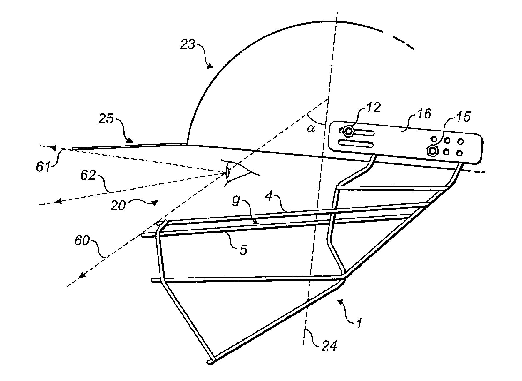
[0030]In FIG. 1, there is shown a cage type face guard 1 made from a frame of struts 2-7.

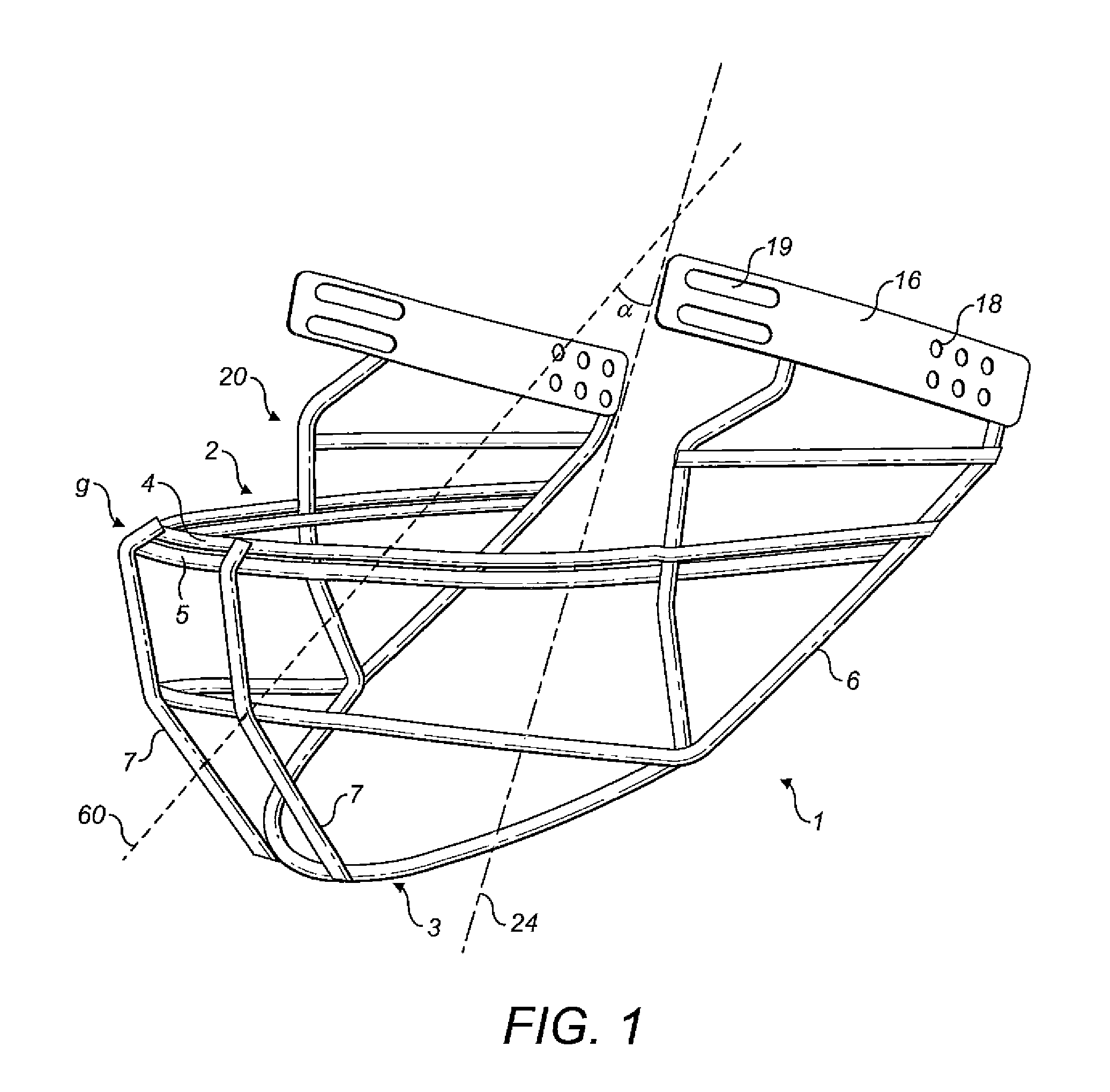
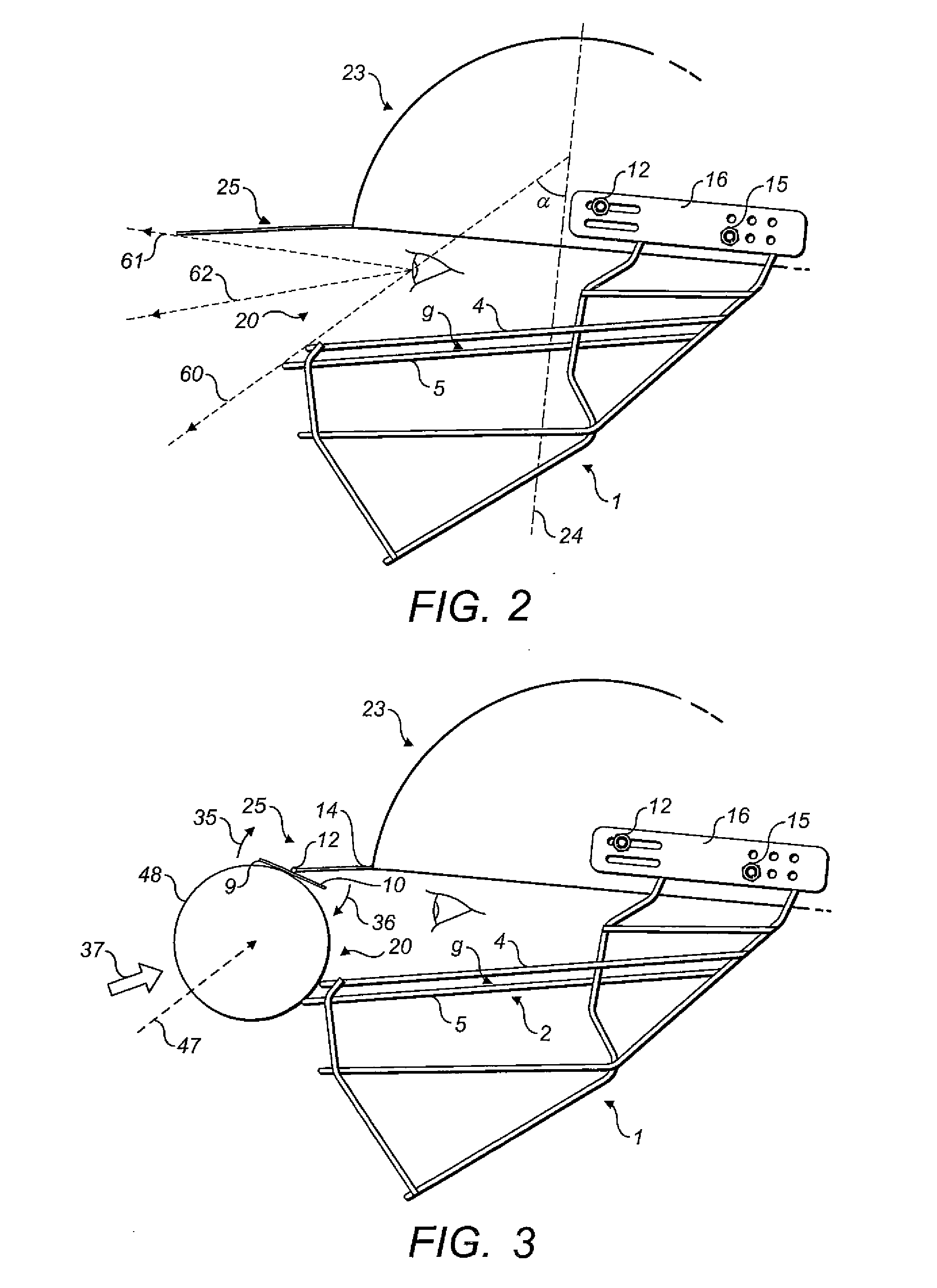
[0031]In this example, the struts 2-7 have a circular cross section although any suitable cross section may be selected. A rearward strut 6 extends at a region which lies beneath and behind the ear of a wearer during use. A lower strut 3 extends in front of and below the chin of a wearer during use. Two generally upright forward struts 7 link the lateral struts which surround the front of a wearer's face. The guard 1 further comprises an open region at its front portion which constitutes a viewing aperture (or viewing gap) 20. A wearer can look forward through the guard 1 though the viewing gap during use of the face guard. In the example of FIG. 1, the viewing gap 20 is completely unobstructed and extends about an arc of at least 180 degrees centred on a vertical axis of symmetry of the guard 1. A viewing axis 60 represents a line of sight of a wearer out through the viewing gap 20. The viewing...


PUM


Abstract

A sports face guard having a cage type construction of interconnected struts, and creating an unobstructed viewing aperture proximate to the eyes of a wearer during use, comprises a forward transverse sill defining at least one boundary of said viewing aperture. The forward transverse sill is comprised of at least two generally transverse struts extending across the front of the face of a wearer during use, said transverse sill having a proximal edge and a distal edge, wherein a first surface of said sill at said distal edge and a second surface of said sill at said proximal edge are spaced linearly apart and lie approximately along a common viewing axis of a wearer during use. The face guard comprises a sill which presents a reduced profile in the field of view of a wearer while presenting an increased surface for contact with an incoming projectile such as a ball, allowing the ball to be impeded and deflected, thereby providing a blocking effect of the guard and reducing the chance of injury to a wearer. The guard may be worn in combination with a helmet and may be secured to a helmet.

Description

[0001]The present invention relates to the field of protective sports equipment for providing facial protection especially in connection with ball sports. Most particularly, the present invention relates to a cage type face guard for use in connection with a helmet.BACKGROUND[0002]Face guards of various types are known. Many designs of face-guards have been suggested for use in connection with ball sports or sports in which a projectile such as a puck is in play. A basic wire mesh type face guard, connectable to a helmet, is known from US 2009 / 0083891. The relatively fine gauge mesh of the guard may make it unsuitable for players of sports requiring a less obstructed line of sight between the players and a moving projectile in play. Another example of a face guard can be seen from WO 2009 / 018442, which shows a hybrid type helmet face mask, wherein the mask incorporates both a visor and a cage and wherein the visor serves to add protection across the field of vision of a wearer, acro...

Claims


Application Information

Patent Timeline
IPC IPC(8): A42B3/20
CPCA42B3/20A42B3/18A42B3/222A42B3/227
Inventor HARDY, JONATHAN JAMES EAN
Owner THE MASURI GRP LTD
Why Eureka
Try Eureka